Single photon emission computed tomography system

a computed tomography and single photon emission technology, applied in the field of single photon emission computed tomography system, can solve the problems of impeded spect imaging's wider implementation, unavailability to all patients, and bulky current spect system

Inactive Publication Date: 2007-01-11
HIGHBROOK HLDG
View PDF31 Cites 31 Cited by
  • Summary
  • Abstract
  • Description
  • Claims
  • Application Information

AI Technical Summary

Problems solved by technology

Despite its many advantages, SPECT imaging is not yet available to all patients who might benefit from it.
Current SPECT instrumentation has a number of disadvantages which have impeded its wider implementation.
Current SPECT systems are bulky, typically requiring a large, dedicated room to house them.
The collimating systems are relatively inefficient, blocking a high percentage of emitted radiation.
Since each detector typically weighs several hundred pounds, the supporting gantry must be large and heavy.
These systems are necessarily large, heavy and expensive.
Although there is great medical need to image patients in a variety of settings, including doctors' offices, emergency rooms and intensive care units, the great size and bulk of current SPECT systems has required them to be in a fixed location, typically a hospital Radiology or Nuclear Medicine department.
Despite these compelling factors, the size and cost constraints of current systems have greatly lim...

Method used


Image

  • Single photon emission computed tomography system
  • Single photon emission computed tomography system
  • Single photon emission computed tomography system

Examples


Embodiment Construction

[0116] Throughout this description, the preferred embodiment and examples shown should be considered as exemplars rather than as limitations on the present invention.

I. General Overview

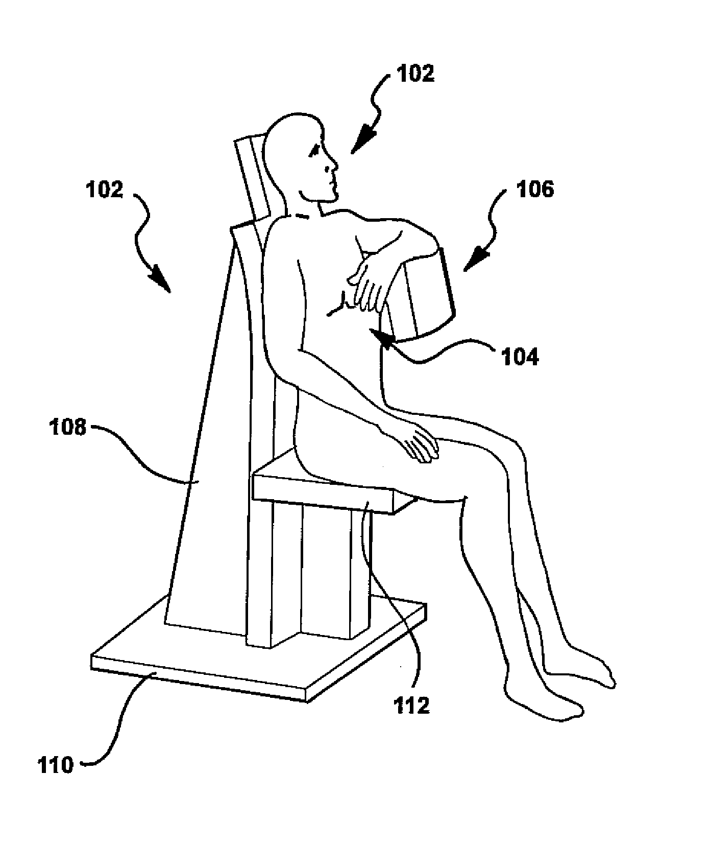
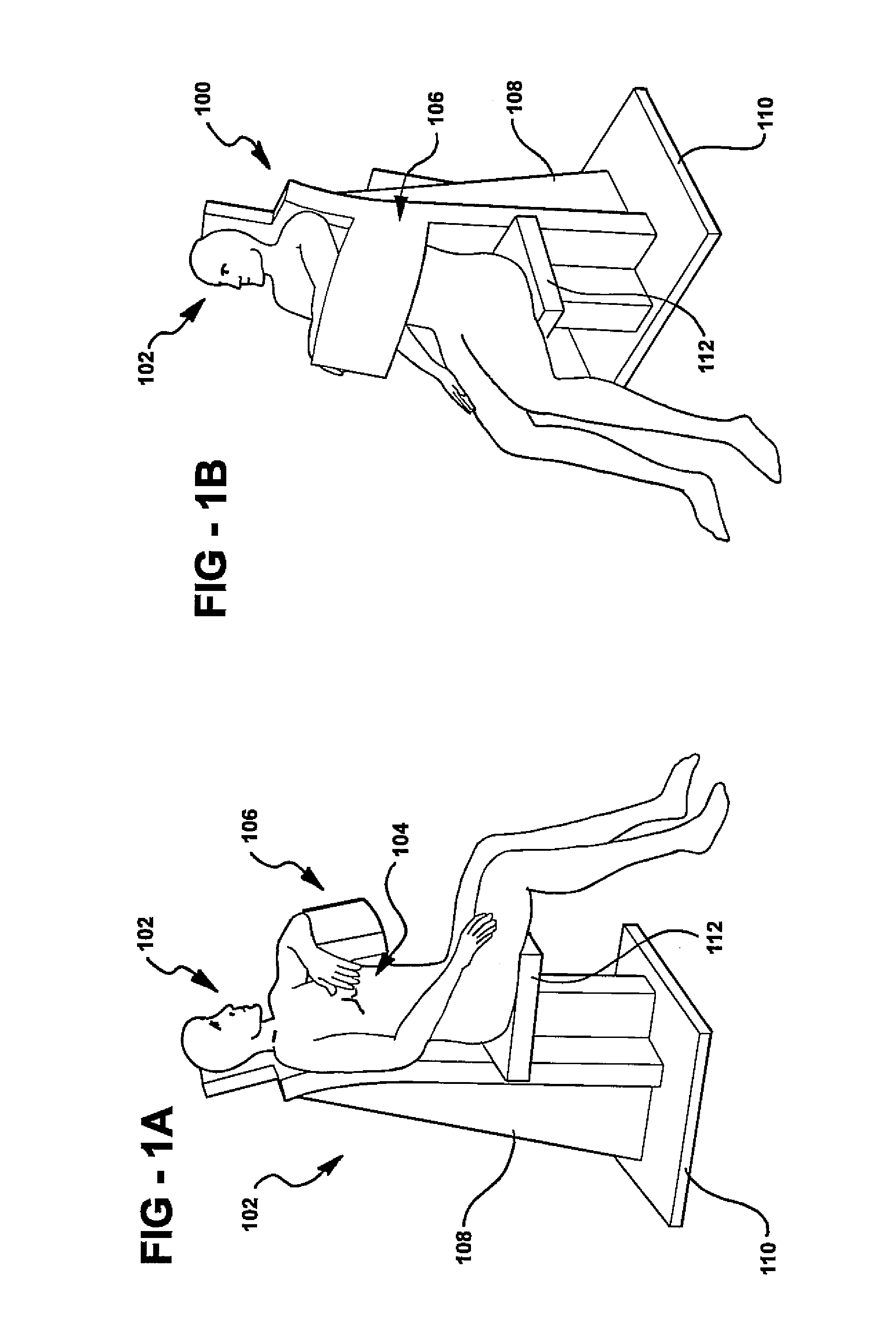
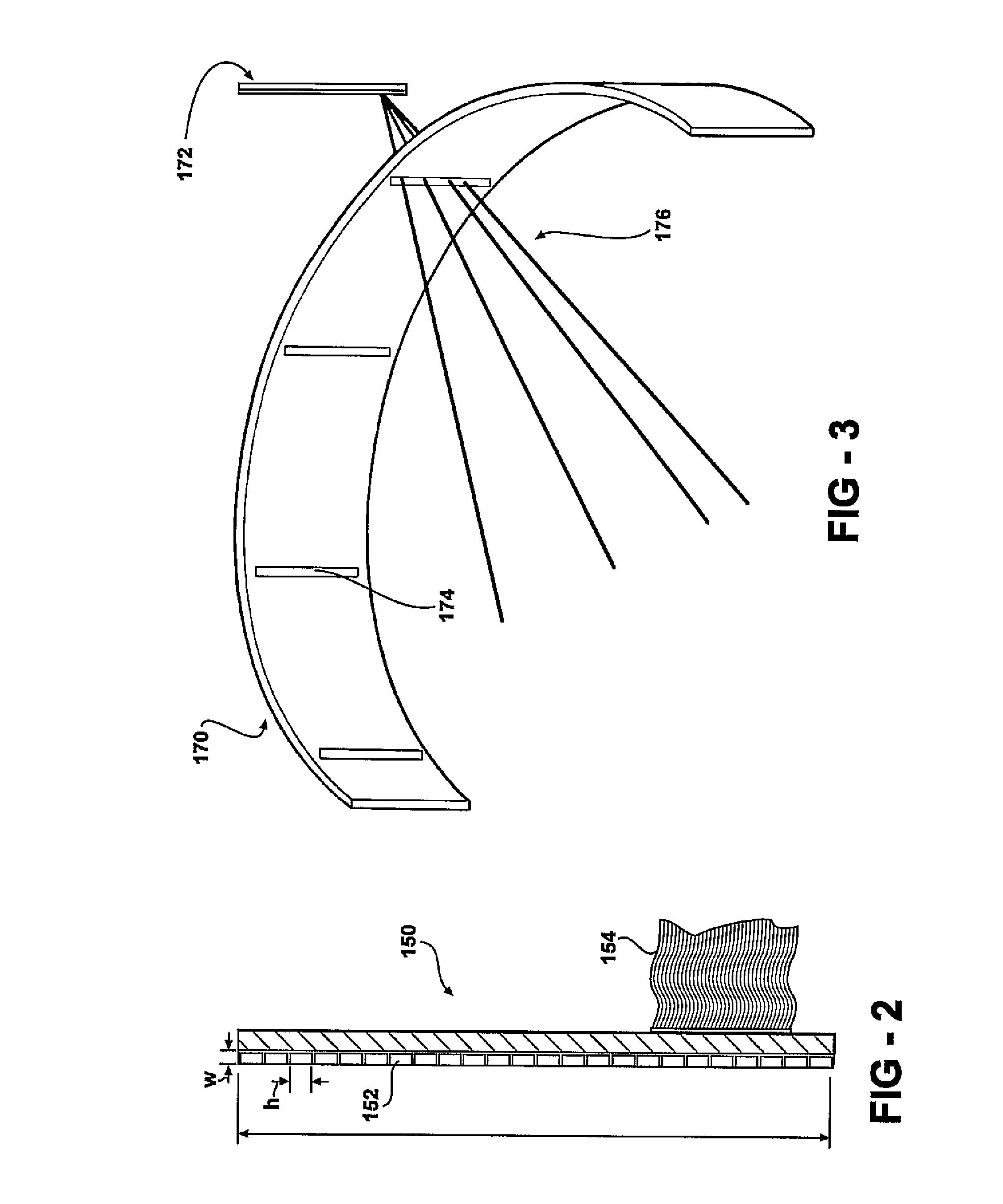
[0117] One aspect of the present invention comprises a system for performing single photon emission computed tomography (SPECT). This system includes a radiation detector assembly consisting of a multiplicity of radiation detector modules preferably positioned around an arc, typically over 180 to 360 degrees. In-plane (axial) collimation is provided by a movable arc or ring extending over an angular range similar to that of the radiation detector assembly (typically 180-360 degrees). Cross-plane (longitudinal) collimation is provided by a plurality of vanes or sheets of photon-attenuating material held in a stationary position and oriented parallel to the transaxial plane (perpendicular to the longitudinal axis). Optionally, these vanes may be separated by sheets of a radiolucent spacer material su...


PUM


Abstract

A single photon emission computed tomography system includes a detector assembly adjacent a field of view and a collimating assembly disposed between the detector assembly and the field of view. The collimating assembly includes at least two spaced-apart collimating vanes of photon-attenuating material. The system further includes a photon-blocking member disposed between the field of view and the detector. The blocking member has an aperture defined therethrough. The system further includes a mask disposed adjacent the detector assembly having at least one aperture defined therethrough. A displacement actuator moves the photon-blocking member relative to the detector assembly.

Description

REFERENCE TO RELATED APPLICATIONS [0001] This application is a continuation-in-part of U.S. patent application Ser. No. 10 / 872,253, filed Jun. 18, 2004, which claims priority to U.S. Provisional Patent Application Ser. No. 60 / 480,381, filed Jun. 20, 2003. U.S. patent application Ser. No. 10 / 872,253 is a continuation-in-part of U.S. patent application Ser. No. 10 / 358,961, filed Feb. 5, 2003, now U.S. Pat. No. 7,015,476 which is a continuation-in-part of U.S. patent application Ser. No. 09 / 549,435, filed Apr. 14, 2000, now U.S. Pat. No. 6,525,320, which claims priority from U.S. Provisional Patent Application Ser. No. 60 / 129,239, filed Apr. 14, 1999 and Ser. No. 60 / 151,378, filed Aug. 30, 1999. This application also claims priority from U.S. Provisional Patent Application Ser. No. 60 / 480,381, filed Jun. 20, 2003, the entire content of all of which are incorporated herein by reference.FIELD OF THE INVENTION [0002] The present invention relates generally to imaging systems and, more spe...

Claims


Application Information

Patent Timeline
IPC IPC(8): G01T1/166
CPCA61B6/037G01T1/1642
Inventor JUNI, JACK
Owner HIGHBROOK HLDG
Why Eureka
Try Eureka