Estimation of an attenuation map based on scattered coincidences in a PET system

a technology of scattered coincidence and attenuation map, which is applied in the field of estimation of attenuation map based on scattered coincidence in pet system, can solve the problems of high computational complexity, inability to reconstruct activity map based on true coincidence alone, and inability to determine relatively rough estimates, so as to reduce computational complexity

Active Publication Date: 2020-01-28
KONINKLJIJKE PHILIPS NV
View PDF3 Cites 2 Cited by
  • Summary
  • Abstract
  • Description
  • Claims
  • Application Information

AI Technical Summary

Benefits of technology

[0009]Therefore, it is an object of the present invention to allow for determining estimates of the attenuation map on the basis of single-scattered coincidences with a reduced computational complexity.
[0011]By merging adjacent grid elements to form a merged image element to which a single attenuation value is assigned, the number of individual attenuation values to be considered in the model calculation is reduced. Hereby, also the number of calculation steps and, thus, the computational complexity is reduced.
[0026]When the model calculation is made on the basis of a relation of the aforementioned kind, the merging of grid elements to one or more merged image elements reduces the number of summands in the sum over b, thereby reducing the computational complexity of the numerical model calculation.

Problems solved by technology

However, it is not possible to reconstruct the activity map based on the true coincidences alone, because not all annihilation photons reach the detector unimpeded due to photon attenuation.
However, this approach does usually only allow to determine relatively rough estimates of the attenuation map.
However, the technique involves a high computational complexity.
This leads to a large number of required calculation steps, which makes the technique relatively slow and impedes its use in practical applications.

Method used


Image

  • Estimation of an attenuation map based on scattered coincidences in a PET system
  • Estimation of an attenuation map based on scattered coincidences in a PET system
  • Estimation of an attenuation map based on scattered coincidences in a PET system

Examples


Embodiment Construction

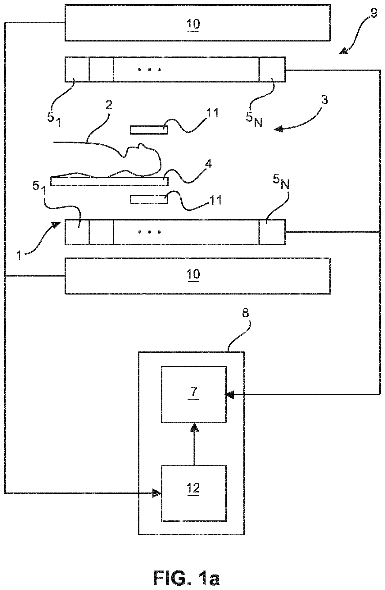
[0043]FIG. 1a schematically and exemplarily shows components of an imaging system for imaging an object 2. In particular, the imaging system may be used in a clinical application. In this case, the object 2 to be imaged may be a human or animal body or a part thereof. The imaging system allows for generating images of the object 2 on the basis of PET measurements using a second imaging modality. In the embodiment depicted in FIG. 1a, the second imaging modality is MRI.

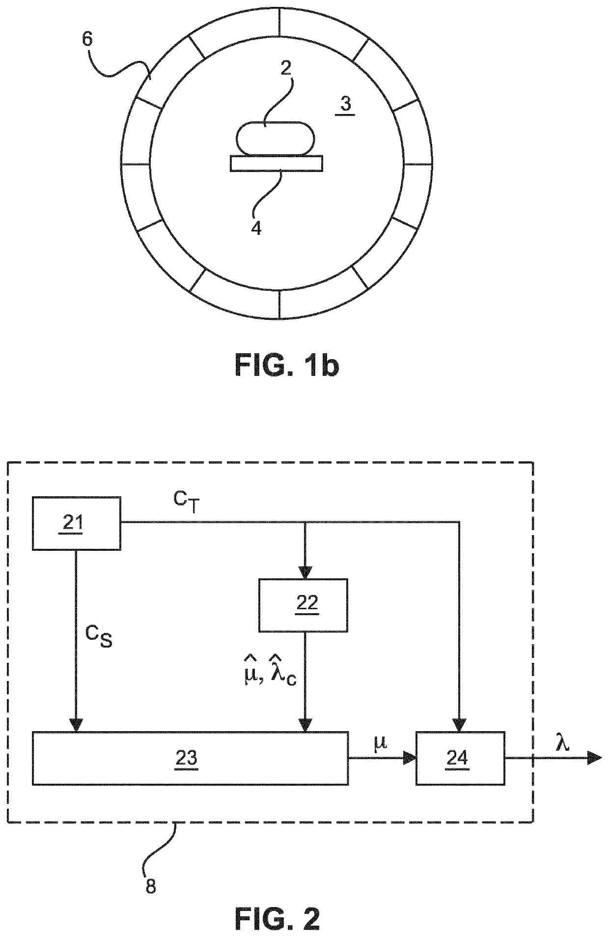
[0044]Thus, the system includes a PET scanner 1 which may include a substantially cylindrical PET scanner volume 3 accommodating the object 2 during operation of the PET scanner 1. In case the object 2 is a human or animal body, it may be supported by a patient table 4 that is movable into and out of the imaging space 3 by means of a controllable drive unit (not shown in the figures).

[0045]The PET scanner volume 3 corresponds to the inner volume defined by a substantially cylindrical detector assembly (which is shown i...


PUM


Abstract

The invention relates to a system for generating an estimate of a photon attenuation map for an object on the basis of single-scattered coincidences measured in a PET scanner. The system comprises a simulation module configured to calculate single-scattered coincidences by a numerical model calculation based on a preliminary attenuation map, where the estimate of the photon attenuation map is generated by adapting at least some attenuation values. The model calculation is made on the basis of a grid covering the object, the grid comprising grid elements (61) to which attenuation values are assigned, and the simulation module is further configured to determine at least one set of adjacent grid elements (61) in order to form a merged image element (63) including the set of adjacent grid elements (61) and to assign a single attenuation value to the merged image element in the model calculation.

Description

CROSS REFERENCE TO RELATED APPLICATIONS[0001]This application is the U.S. National Phase application under 35 U.S.C. § 371 of International Application No. PCT / EP2016 / 060363, filed May 10, 2016, published as WO 2016 / 184712 on Nov. 24, 2016, which claims the benefit of European Patent Application Number 15168181.4 filed May 19, 2015. These applications are hereby incorporated by reference herein.FIELD OF THE INVENTION[0002]The invention relates to a method and a system for generating an estimate of a photon attenuation map on the basis of measurements of single-scattered coincidences in a Positron Emission Tomography (PET) system. Moreover, the invention is related to a computer program causing a processor to carry out the method.BACKGROUND OF THE INVENTION[0003]In PET, a positron-emitting substance is injected into a human or animal body or into another object to be monitored. The substance, which is usually also referred to as radio pharmaceutical or radiotracer, is selected such t...

Claims


Application Information

Patent Timeline
Patent Type & Authority Patents(United States)
IPC IPC(8): A61B6/00G01R33/48A61B6/03G06T7/00G06T11/00
CPCA61B6/5247A61B6/5205A61B6/4417G06T7/0012G06T11/006A61B6/037G01R33/481A61B6/5282G06T2207/10088G06T2207/10104A61B6/5235A61B5/055A61B5/0035G06T11/005
Inventor BERKER, YANNICKSCHULZ, VOLKMAR
Owner KONINKLJIJKE PHILIPS NV
Why Eureka
Try Eureka