Single photon emission computed tomography instrument and the operating method thereof

a single photon emission and computed tomography technology, applied in the field of single photon emission computed tomography (spect) instruments and the operating method thereof, can solve the problems of ghost artifacts, difficult manufacturing, and high cost of spect scanners using pinhole collimators

Inactive Publication Date: 2014-03-04
IND TECH RES INST
View PDF10 Cites 29 Cited by
  • Summary
  • Abstract
  • Description
  • Claims
  • Application Information

AI Technical Summary

Problems solved by technology

Therefore, SPECT scanner using pinhole collimator can be very expensive, not to mention that it can be very difficult to manufacture.
However, in a situation when the pinhole collimator is enabled to rotate about the scanned object in a circular orbit for acquiring projections, it is more than often that there are ghost artifacts appeared on the recontruction image due to certain mechanical assembly inaccurqacy as the pinhole collimator can be very heavy.
However, since each pinhole on the cylindric pinhole collimator is a micro aperature that is formed with a width smaller than 1 millimeter, such cylindric pinhole collimator can be very expensive and difficult to build.

Method used


Image

  • Single photon emission computed tomography instrument and the operating method thereof
  • Single photon emission computed tomography instrument and the operating method thereof
  • Single photon emission computed tomography instrument and the operating method thereof

Examples


first embodiment

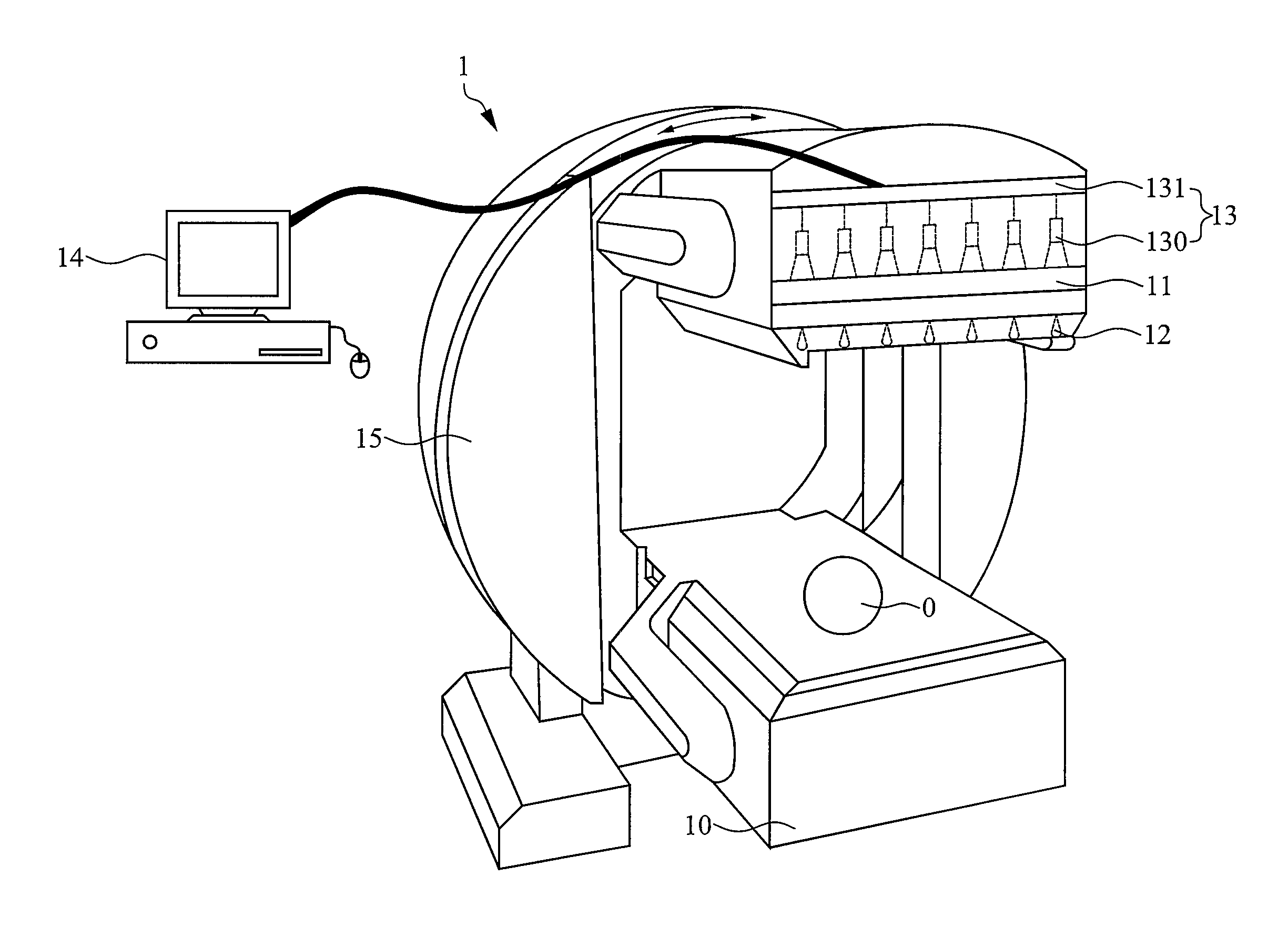
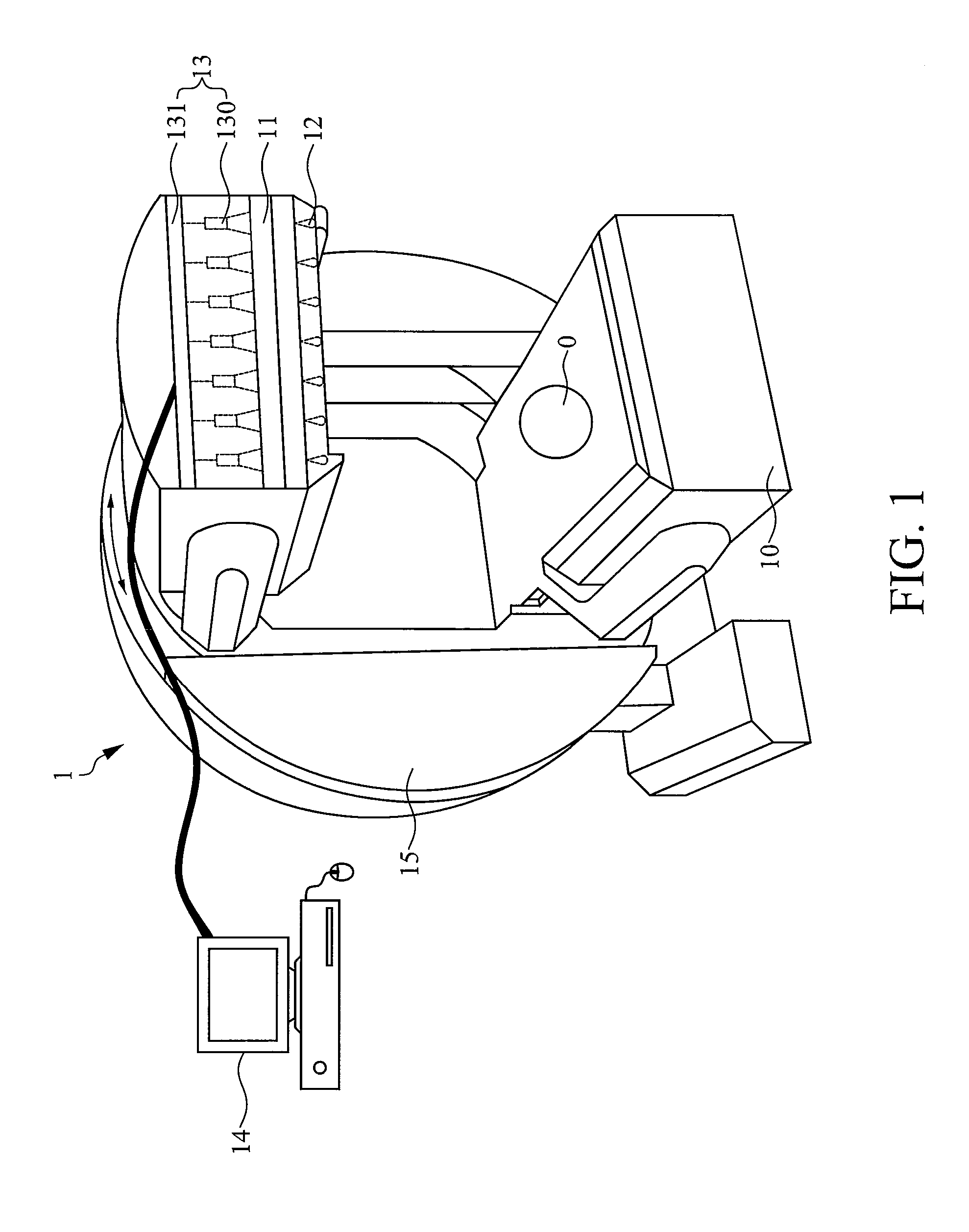
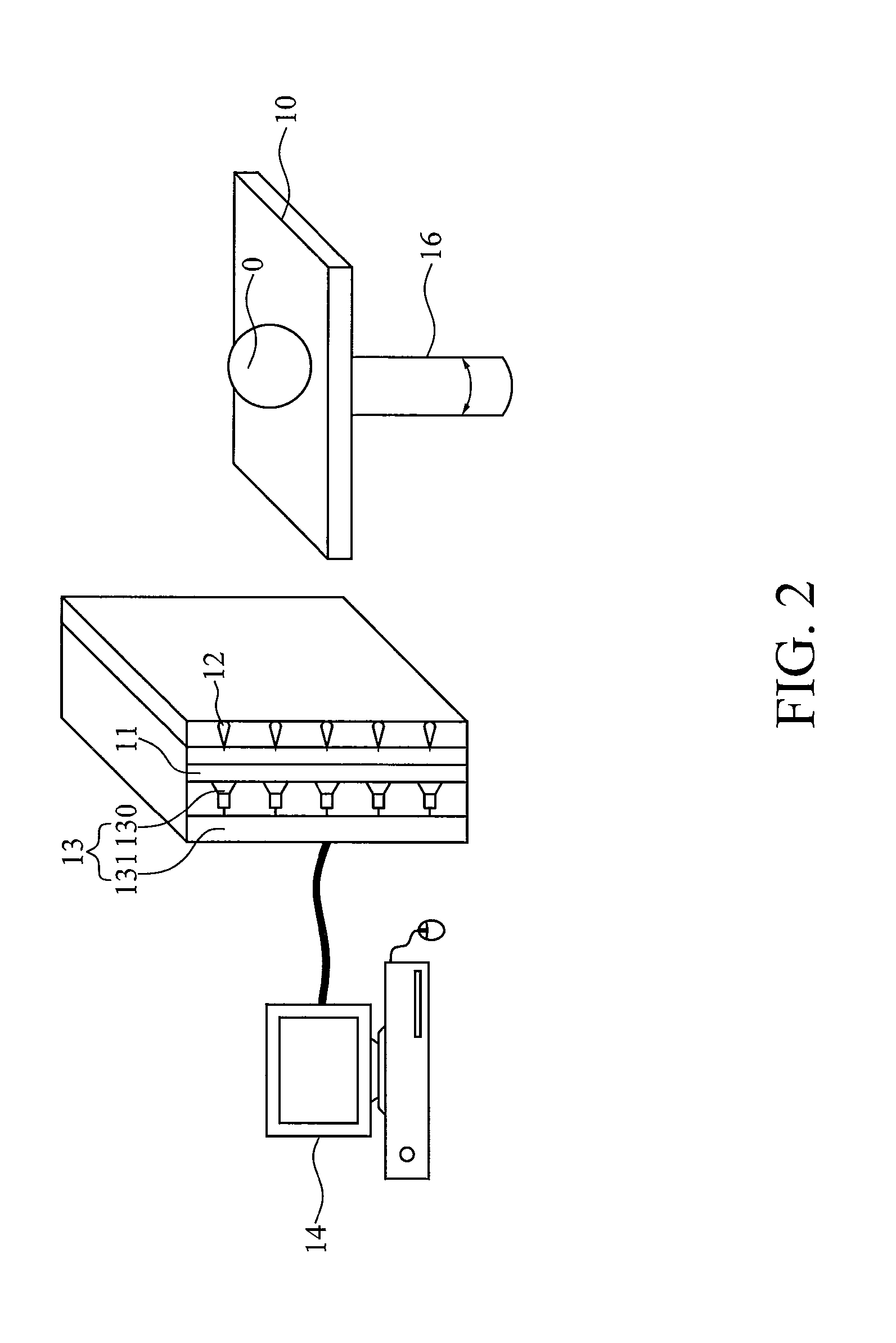
[0018]Please refer to FIG. 1, which is a schematic diagram showing a SPECT instrument according to the present disclosure. In FIG. 1, the present disclosure provides a single photon emission computed tomography (SPECT) instrument 1, which comprises: a platform 10; at least one detector 11, each disposed at one side of the platform 10; at least one beam stopper 12, each disposed at a position between the platform 10 and the at least one detector 11; a signal processing device 13, electrically connected to the at least one detector 11 for communicated with the same; and a computing device 14, electrically connected to the signal processing device 13 for communicated with the same. In addition, the signal processing device 13 further comprises: a signal conversion / amplification unit 130 and a signa; filtering unit 131. In this embodiment the signal conversion / amplification unit is substantially a photomultiplier tube, and the signal filtering unit is substantially an energy discriminat...

third embodiment

[0022]Please refer to FIG. 3, which is a schematic diagram showing a SPECT instrument according to the present disclosure. In this embodiment, instead of only one detection assembly, there are more than one detection assemblies being included in the SPECT instrument that are respectively disposed surrounding the scanned object 0 so as to acquire images of the scanned object respectively at a specific detection angle, whereas each detection assembly is comprised of: at least one beam stopper 12, at least one detector 11 and a signal processing device 13. Moreover, each signal processing device 13 is connected to a computing device 14 so as to transmit the scanning result to the computing device 14 for processing. As the embodiment shown in FIG. 3, there are four sets of detection assemblies being included in the SPECT instrument, however, it is noted that the amount of detection assembly as well as the distance between any two neighboring detection assemblies and the respective dista...

fourth embodiment

[0023]Please refer to FIG. 4, which is a schematic diagram showing a SPECT instrument according to the present disclosure. In this embodiment, there are a plurality of beam stoppers 12 being disposed into a ring-shaped formation surrounding the scanned object 0 while allowing the scanned object 0 to be positioned at the center of the ring-shaped formation. In the embodiment shown in FIG. 4, as the plural beam stoppers 12 are uniformly embedded on the wall of a hollow cylinder, the plural beam stoppers 12 are disposed into a ring-shaped formation surrounding the scanned object 0. Moreover, for enabling beams of radiation can only be absorbed by those beam stoppers 12, the hollow cylinder should be made of a material of low atomic number and low density. In this embodiment, the hollow cylinder is made of carbon fiber, but is not limited thereby. In addition, the arrangement of the plural beam stoppers 12 is also not being limited to the ring-shaped formation. For perverting projection...


PUM


Abstract

A single photon emission computed tomography instrument is provided, which has a platform, at least one detector, at least one beam stopper, a signal processing device and a computer. The at least one detector is disposed at one side of the platform, and the at least one beam stopper is disposed between the platform and the detector. The signal processing device is electrically communicated with the at least one detector, and the computer is electrically communicated with the signal processing device. The present disclosure further provides an operating method which the beam stopper is added or removed respectively while scanning an analyze by the single photon emission computed tomography instrument in different angles. The projection dataset emitted from the focus could be estimated by subtracting the projecting data without the beam stopper from that with the beam stopper, and high resolution image could be obtained by using image reconstruction program.

Description

TECHNICAL FIELD[0001]The present disclosure relates to a single photon emission computed tomography (SPECT) instrument and the operating method thereof, and more particularly, to a single photon emission computed tomography instrument operated basing upon the use of beam stoppers for absorbing beams of radiation.TECHNICAL BACKGROUND[0002]The application of single photon emission computed tomography (SPECT) technique in molecular imaging is becoming more and more popular, as it can be performed without requiring any accelerator and also it can produce required images in an instant manner, due to the radioisotope that is commonly used by SPECT imaging has a comparatively longer half-life period. Recently, SEPCT scanner is becoming the essential instrument for many animal studies relating to internal orgasm whichever requires sharp images with very accurate spatial and contrast resolutions.[0003]Conventionally, the animal SPECT scanner is generally configured with pinhole collimator, w...

Claims


Application Information

Patent Timeline
Patent Type & Authority Patents(United States)
IPC IPC(8): G01T1/166
CPCA61B6/037A61B6/4266A61B6/06
Inventor CHUANG, KEH-SHIH
Owner IND TECH RES INST
Why Eureka
Try Eureka