Current fault detector and circuit interrupter and packaging thereof

a current fault and circuit interrupter technology, applied in the field of current fault detector and circuit interrupter, aircraft electrical control system, can solve the problems of fuel vessel breach, inconvenient rewiring of aircraft, and limitations of prior art systems

Inactive Publication Date: 2006-02-09
HYDRO AIRE INC
View PDF3 Cites 20 Cited by
  • Summary
  • Abstract
  • Description
  • Claims
  • Application Information

AI Technical Summary

Benefits of technology

[0016] In another facet, the invention relates to a device for closing a current path between the line side and the load side of an electrical circuit. The device includes a power controller having an opened position and a closed position. The power controller is located within the current path and switches from the open position to the closed position in the presence of a first control supply and maintains the closed position in the presence of a second control supply. The device further includes a power supply which, when the power controller is open, outputs the first control supply having a first voltage for a first amount of time and after the first amount of time, outputs the second control supply having a second voltage, less than the first voltage and sufficient to hold the power controller in the closed position.
[0017] In another aspect, the invention relates to a device for interrupting a current path between the line side and the load side of an electrical circuit that is connected to an electrical load having an associated first operating current for a first amount of time and a second operating current for a second amount of time. The device includes a power controller that is positioned within the current path. The power controller closes the current path in the presence of a control supply and opens the current path in the absence of the control supply. The device also includes a sensor system that monitors the current in the current path and outputs a sensor signal indicative of a current condition within the current path. The device further includes a logic controller that receives the sensor signal and during the first amount of time compares the sensor signal to a first established criteria defined by the first operating current and removes the control supply from the power controller if the sensor signal does not satisfy the first established criteria. During the second amount of time, the logic controller compares the sensor signal to a second established criteria defined by the second operating current and removes the control supply from the power controller if the sensor signal does not satisfy the second established criteria.

Problems solved by technology

In the electromechanical arts, current imbalances are indicative of serious problems that can lead to disastrous results, such as arcing within fuel pumps.
Since fuel pumps are often housed within a fuel vessel to directly pump fuel out of the vessel, arcing within a fuel pump can lead to an explosion of fuel-air mixture and a subsequent breach of the fuel vessel, which can be catastrophic.
One very important form of current imbalance is a ground fault in which current is flowing between a circuit or electrical device to ground, when such current flow is not desired.
However, such prior art systems have had limitations, including the necessity of rewiring the aircraft.
In addition to the requirement to rewire the aircraft, additional space had to be found to accommodate the ground fault interruption system.
It would further be desirable for the circuit protection device to be included within an existing device in the aircraft, or to be packaged with an existing device, sharing the same connections to existing electrical circuits, since space for avionics is limited in any aircraft and adding wiring to accommodate a new device is very difficult.

Method used


Image

  • Current fault detector and circuit interrupter and packaging thereof
  • Current fault detector and circuit interrupter and packaging thereof
  • Current fault detector and circuit interrupter and packaging thereof

Examples


Embodiment Construction

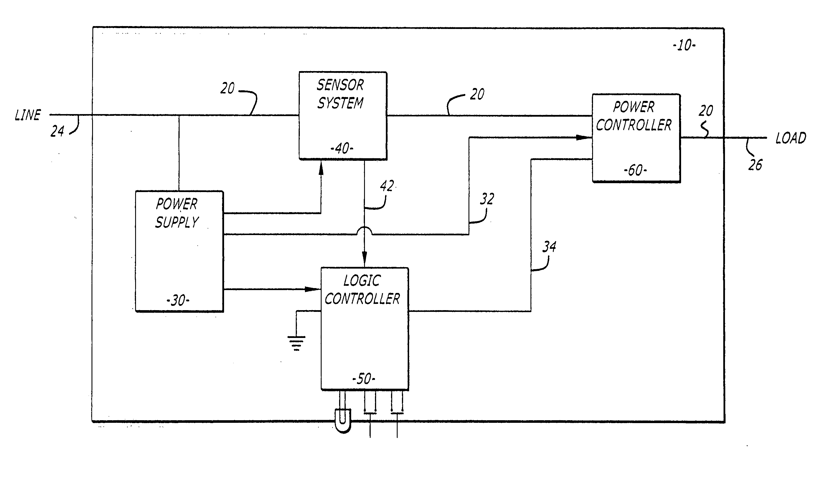
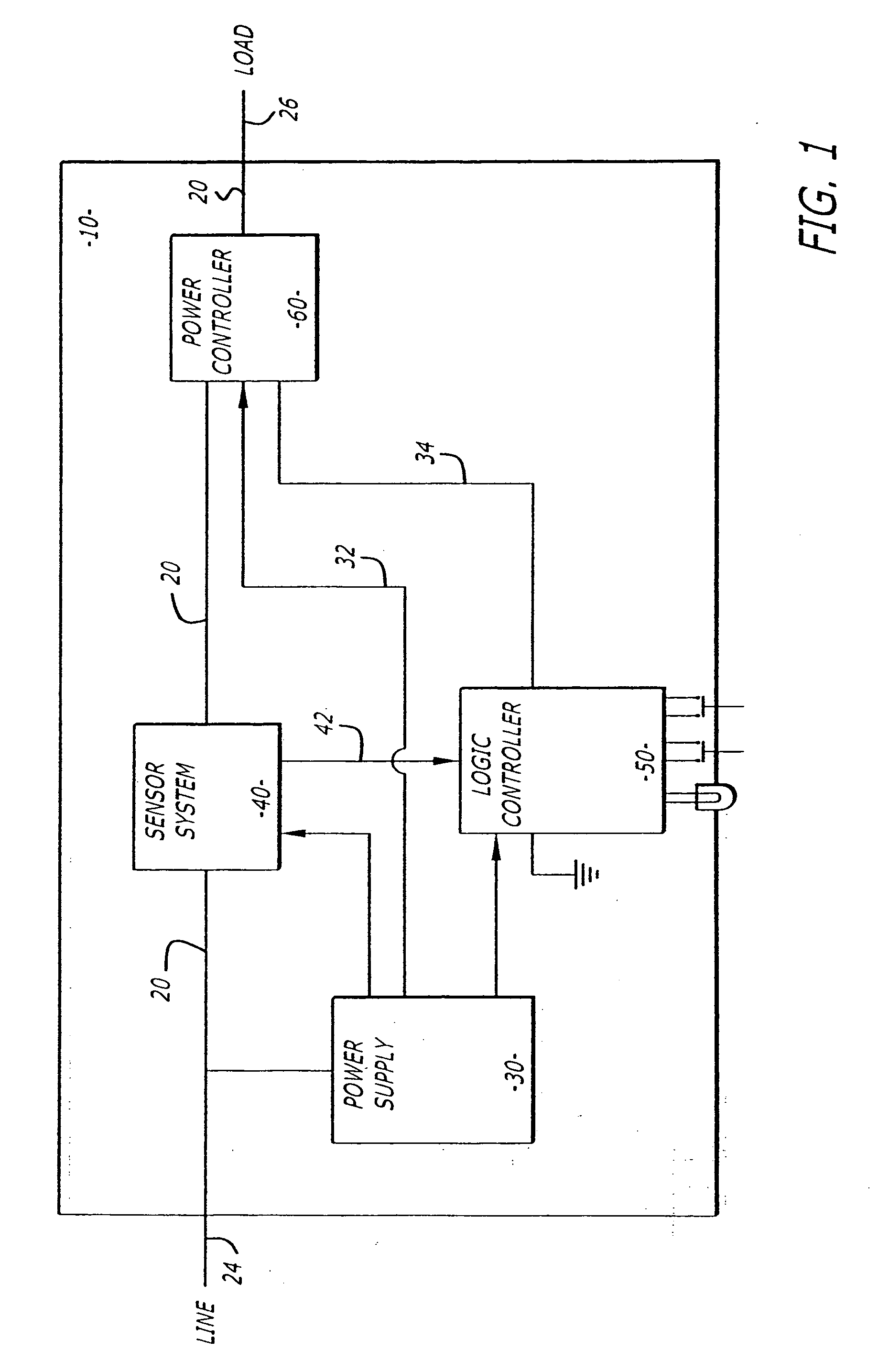
[0061] Referring now to the drawings, which are provided for purposes of illustration and not by way of limitation, and particularly to FIG. 1, there is shown a system 10 constructed in accordance with the present invention for interrupting a current path 20 between the line side 24 and the load side 26 of an electrical circuit upon detection of a current fault-condition within the electrical circuit. A current fault-condition may be the result of a current imbalance condition or an over-current condition within the electrical circuit.

[0062] In one of its most basic forms, the system 10 includes a power supply 30, a sensor system 40, a logic controller 50 and a power controller 60. The power supply 30 provides power to the logic controller 50, the sensor system 40 and the power controller 60. The power controller 60 may be an electromechanical relay, either AC coil or DC coil, or a solid state device. Coil type relays are powered by a control supply 32 provided by the power supply....


PUM


Abstract

A power controller is positioned within a current path between the line side and the load side of an electrical circuit. The power controller closes the current path in the presence of a control supply and opens the current path in the absence of the control supply. A power supply electrically connected to the current path provides the control supply. A sensor system receives power from the power supply, monitors the current in the current path and outputs a sensor signal indicative of a current condition within the current path. A logic controller also receives power from the power supply, receives the sensor signal and removes the control supply from the power controller when the sensor signal does not satisfy an established criteria. The sensor system may include one or both of an imbalance sensor for monitoring the current balance among two or more electrical lines and over-current sensors for monitoring current in individual lines.

Description

RELATED APPLICATIONS [0001] This is a continuation-in-part of application Ser. No. 09 / 954,474, filed Sep. 14, 2001 which is a continuation-in-part of application Ser. No. 09 / 775,337, filed Feb. 1, 2001.BACKGROUND OF THE INVENTION [0002] 1. Field of the Invention [0003] This invention relates generally to electrical control systems, and more specifically to an aircraft electrical control system that monitors the current condition in a current path and interrupts the current path upon detection of a current fault. [0004] 2. Description of the Related Art [0005] In the electromechanical arts, current imbalances are indicative of serious problems that can lead to disastrous results, such as arcing within fuel pumps. Since fuel pumps are often housed within a fuel vessel to directly pump fuel out of the vessel, arcing within a fuel pump can lead to an explosion of fuel-air mixture and a subsequent breach of the fuel vessel, which can be catastrophic. In light of the seriousness of such a...

Claims


Application Information

Patent Timeline
Patent Type & Authority Applications(United States)
IPC IPC(8): H02H3/08H01H83/02H01H83/04H02H3/16H02H1/06H02H3/04H02H3/087H02H3/10H02H3/347H02J1/00
CPCH01H83/226H02H1/06H02H3/347H02H3/105H02H3/335H02H3/04
Inventor BAX, RONALD A.RUSALI, RUDY H.KING, TIMOTHY E.
Owner HYDRO AIRE INC
Why Eureka
Try Eureka