Hinge frame for portable computer and structure for mounting the same

a portable computer and hinge frame technology, applied in the field of portable computers, can solve the problems of insufficient handling of the increased load present in the relatively larger portable computers, the inconvenience of adding an additional metal plate, and the weakened strength of the portable computer, so as to minimize the space required for installing the latch and minimize the number of parts. the effect of the latch assembly

Inactive Publication Date: 2006-02-09
LG ELECTRONICS INC
View PDF9 Cites 8 Cited by
  • Summary
  • Abstract
  • Description
  • Claims
  • Application Information

AI Technical Summary

Benefits of technology

[0011] An object of the present invention is to provide a latch device that securely engages a main body and a display to each other and easily operates in relatively large portable computers.
[0012] Another object of the present invention is to provide a latch device that makes it possible to minimize a space required to install a latch and a plurality of hooks typically operated by a release mechanism.
[0013] Another object of the present invention is to provide a latch device that makes it possible to minimize the number of parts in the latch assembly.

Problems solved by technology

However, the hinge frames 16 of the background art merely secure the hinge unit 7 to the main body 1, and are not sufficient to handle the increased loading that is present in the relatively larger, portable computers.
In addition, there is the added inconvenience of an additional metal plate that should be installed to cover the connectors 13 and the power jack 14 to prevent electromagnetic waves from leaking to the surroundings through the connectors 13, the power jack 14 and the like.
Therefore, there is a further problem in that a portion adjacent to the cut-away portion is relatively narrowed and its strength is thus weakened.

Method used


Image

  • Hinge frame for portable computer and structure for mounting the same
  • Hinge frame for portable computer and structure for mounting the same
  • Hinge frame for portable computer and structure for mounting the same

Examples


Embodiment Construction

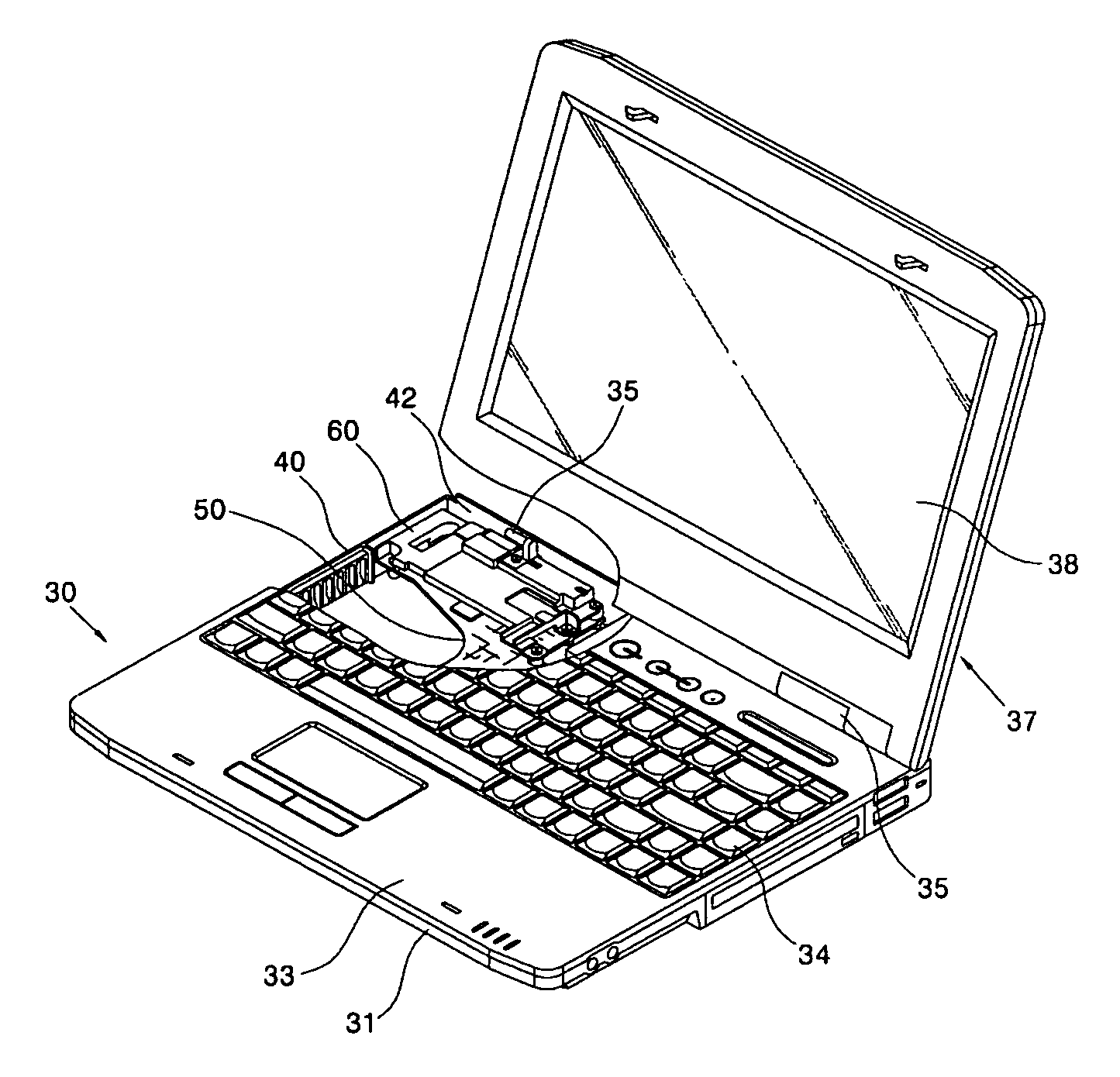
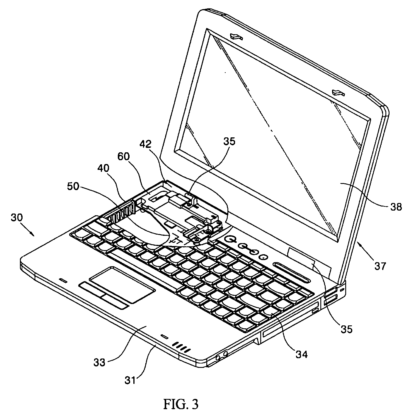
[0041] The present invention will be described hereinafter with reference to the accompanying drawings. FIG. 3 is a partially cut-away, perspective view showing the configuration of a portable computer having a hinge frame according to a first embodiment of the present invention. FIG. 4 is a partially cut-away, exploded perspective view showing the configuration of the first embodiment of the present invention. FIG. 5a is a plan view showing the configuration of the hinge frame according to the first embodiment of the present invention. FIG. 5b is a rear view showing the configuration of the hinge frame according to the first embodiment of the present invention. FIG. 5c is a side view showing the configuration of the hinge frame according to the first embodiment of the present invention. FIG. 5d is a bottom view showing the configuration of the hinge frame according to the first embodiment of the present invention.

[0042] Referring to these figures, a bottom case 31 and a keyboard d...


PUM


Abstract

The present invention relates to a hinge frame for a portable computer and a structure for mounting the same. The hinge frame of the present invention comprises a frame body through which a plurality of fastening holes are perforated, a hinge fastening portion which is formed at a portion of the hinge body and to which a hinge unit is fastened, and a plurality of covering portions which are formed along an edge of the frame body and cause parts mounted on a board to be seated therein. The present invention provides the advantages of the hinge unit being more firmly fixed to the main body, improved installation strength of connectors and the like mounted on the main board, and relatively reinforcement of the main board.

Description

CROSS-REFERENCES TO RELATED APPLICATIONS [0001] This nonprovisional application claims the benefit of Korean Application Nos. P2004-052462, filed on Jul. 6, 2004, and P2004-052466 filed on Jul. 6, 2004, the entirety of each of which are hereby incorporated by reference. BACKGROUND OF THE INVENTION [0002] 1. Field of the Invention [0003] The present invention relates to a portable computer. More particularly, the present invention relates to a hinge frame permitting a hinge assembly to be fixed to a main body of a portable computer and a structure for mounting the same. [0004] 2. Description of the Background Art [0005] A hinge frame is a component for securing a portion of a hinge assembly for allowing a display unit to be pivoted on a main body of a portable computer. In general, the hinge frame is installed in the main body of the portable computer. FIG. 1 shows the external configuration of a general portable computer of the background art. A main body 1 of the portable computer ...

Claims


Application Information

Patent Timeline
Patent Type & Authority Applications(United States)
IPC IPC(8): G06F1/16
CPCG06F1/1616G06F1/203G06F1/1683G06F1/1656
Inventor NA, SANG-JUJIN, BYOUNG-YOON
Owner LG ELECTRONICS INC
Why Eureka
Try Eureka