Image fixing apparatus stably controlling a fixing temperature, and image forming apparatus using the same

a technology of fixing apparatus and fixing temperature, which is applied in the direction of electrographic process, electric/magnetic/electromagnetic heating, instruments, etc., can solve the problem that the electromagnetic induction fixing mechanism cannot ensure that the temperature increase at the longitudinal end side of the fixing member is suppressed, and the surface temperature of the fixing belt is uneven

Inactive Publication Date: 2006-02-09
RICOH KK
View PDF21 Cites 177 Cited by
  • Summary
  • Abstract
  • Description
  • Claims
  • Application Information

AI Technical Summary

Problems solved by technology

This causes a generation of Joule heat due to an electrical resistance of the support roller itself.
However, the electromagnetic induction type fixing mechanism cannot make sure to suppress a temperature increase at longitudinal end sides of the fixing member, e.g., the fixing belt or roller, which may be overly heated, especially, when the image forming operation is consecutively performed on a narrower-sized recording sheet.
This results in an uneven surface temperature of the fixing belt.
This problem occurs typically when the image forming is consecutively performed to a relatively small size recording sheet.
If the image forming operation is performed to a relatively large size recording sheet under this condition, a troublesome phenomenon referred to as a hot off-set may be caused at a surface area of the fixing belt where the fixing temperature is too high.
As a result, the toner image on the recording sheet loses a portion thereof.
If the temperature is partly risen on the surface of the fixing belt in excess of a predetermined range of the fixing temperature, the fixing belt may cause a thermal breakdown.
If the image forming operation is performed under this condition, another troublesome phenomenon referred to as a cold off-set may be caused at a surface area of the fixing belt where the fixing temperature is too low.
As a result, the toner image on the recording sheet loses a portion thereof.

Method used


Image

  • Image fixing apparatus stably controlling a fixing temperature, and image forming apparatus using the same
  • Image fixing apparatus stably controlling a fixing temperature, and image forming apparatus using the same
  • Image fixing apparatus stably controlling a fixing temperature, and image forming apparatus using the same

Examples


Embodiment Construction

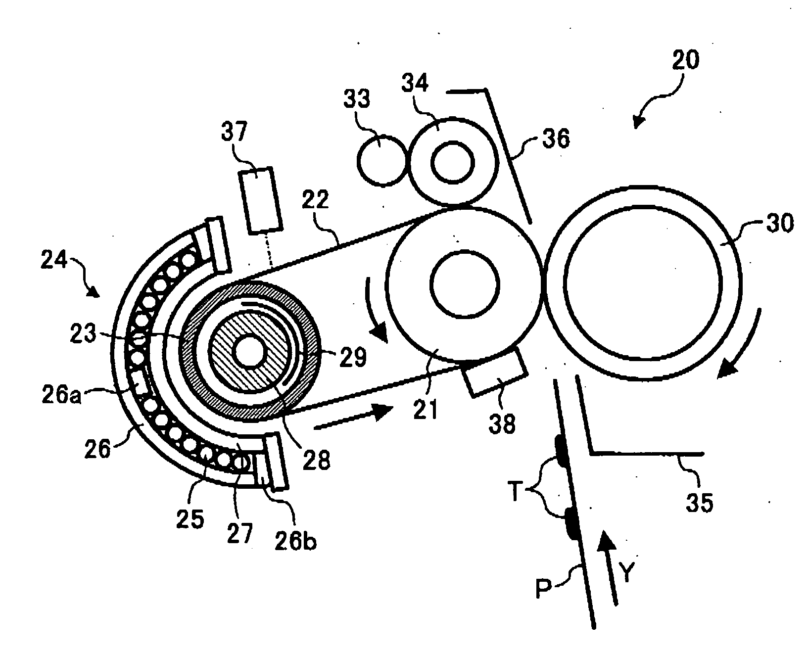
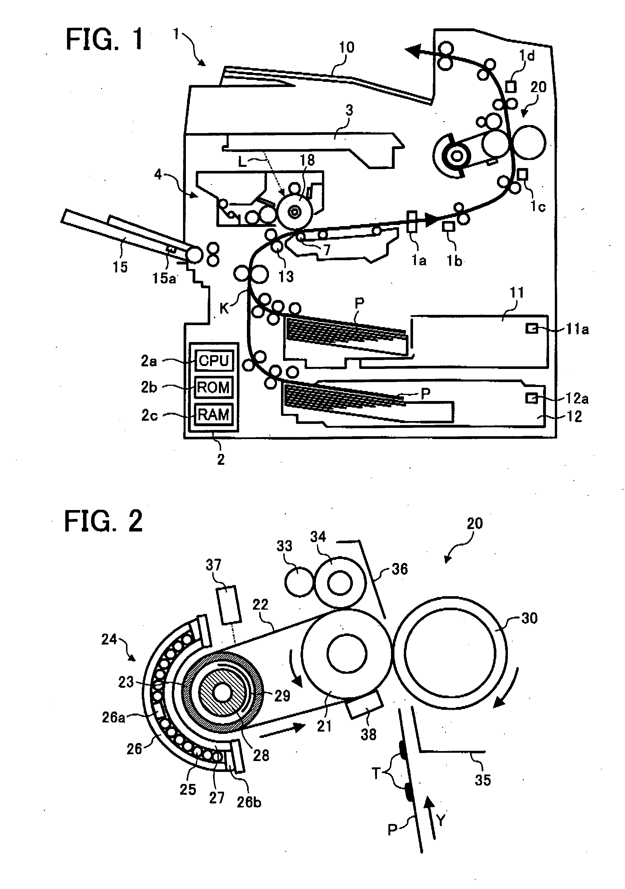
[0042] In describing preferred embodiments illustrated in the drawings, specific terminology is employed for the sake of clarity. However, the disclosure of this patent specification is not intended to be limited to the specific terminology so selected and it is to be understood that each specific element includes all technical equivalents that operate in a similar manner. Referring now to the drawings, wherein like reference numerals designate identical or corresponding parts throughout the several views, particularly to FIG. 1, an image forming apparatus 1 according to an embodiment of the present invention is explained. The image forming apparatus 1 illustrated in FIG. 1 is a laser printer as one example of the embodiment of the present invention. As shown in FIG. 1, the image forming apparatus 1 includes a control circuit unit 2, an exposure unit 3, a process cartridge 4, an image transfer unit 7, an output tray 10, sheet cassettes 11 and 12, a registration roller 13, a manual i...


PUM


Abstract

An image forming apparatus includes an image forming mechanism and an image fixing unit. The image forming mechanism forms a toner image on a recording sheet. The image fixing unit fixes the toner image onto the recording sheet. The image fixing unit includes a magnetic flux generator, a heat member, a magnetic flux adjuster, and a controlling member. The magnetic flux generator generates a magnetic flux. The heat member is heated inductively by the magnetic flux generated by the magnetic flux generator. The magnetic flux adjuster reduces the magnetic flux active on the heat member to form a heat reduction area in an outer circumferential surface of the heat member in a width direction thereof. The controlling member moves the magnetic flux adjuster to change the heat reduction area.

Description

BACKGROUND OF THE INVENTION [0001] 1. Field of the Invention [0002] The present invention relates to an image forming apparatus, and more particularly to an image fixing apparatus which uses an induction heater and is capable of stably controlling a fixing temperature. [0003] 2. Discussion of the Background [0004] A background image forming apparatus such as a copy machine, a printer, a facsimile machine, and a multi-function machine capable of copying, printing, and faxing uses an electromagnetic induction type fixing mechanism to reduce a machine rise time for an energy savings. [0005] One example of the electromagnetic induction type fixing mechanism includes a support roller, an auxiliary fixing roller, a fixing belt, a magnetic flux generator, and a pressure roller. The support roller serves as a heat roller, and the auxiliary fixing roller serves as a fixing roller. The fixing belt has a heat resistant property and is extended between the support roller and the auxiliary fixin...

Claims


Application Information

Patent Timeline
Patent Type & Authority Applications(United States)
IPC IPC(8): G03G15/20
CPCG03G2215/2016G03G15/2053G03G15/2042G03G2215/2032
Inventor ISHII, KENJIAMITA, AKIYASUOMURA, KENHASEGAWA, KENICHIYOKOYAMA, HIROSHIUENO, SATOSHI
Owner RICOH KK
Why Eureka
Try Eureka