Devices, systems, and methods employing a molded nerve cuff electrode

a nerve cuff electrode and molded technology, applied in the field of nerve cuff electrodes, can solve the problems of inability to fully adapt to the electrode, the spiral cuff electrode does not have a reliable interface with small nerves, and the patent to produce the electrode is labor-intensiv

Active Publication Date: 2006-02-09
SPR THERAPEUTICS
View PDF5 Cites 217 Cited by
  • Summary
  • Abstract
  • Description
  • Claims
  • Application Information

AI Technical Summary

Problems solved by technology

Existing spiral cuff electrode do not reliability interface to small nerves.
The stiffness also does not allow the electrode to be fully adaptive, accommodating po

Method used


Image

  • Devices, systems, and methods employing a molded nerve cuff electrode
  • Devices, systems, and methods employing a molded nerve cuff electrode
  • Devices, systems, and methods employing a molded nerve cuff electrode

Examples


Embodiment Construction

I. Molded Nerve Cuff

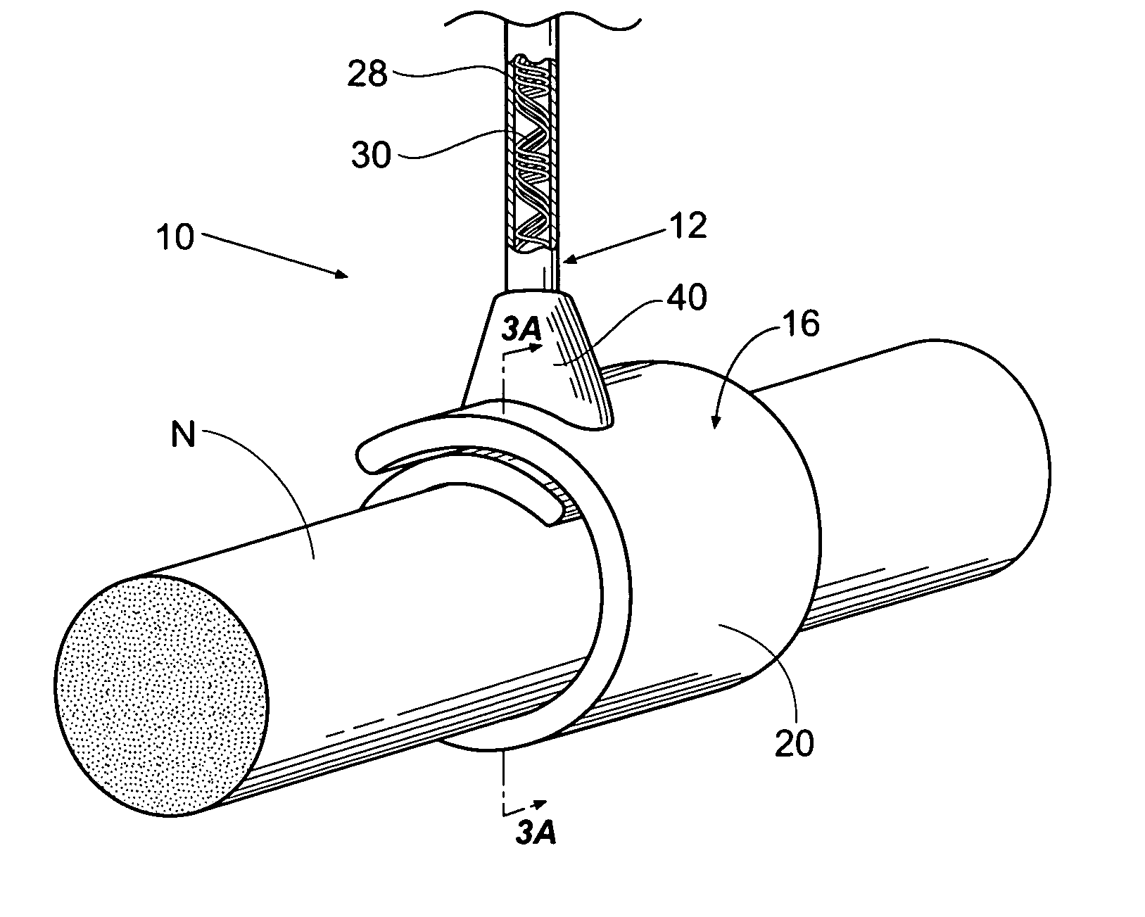
[0032]FIG. 1 shows an implant system 10 for recording, and / or stimulation, and / or blocking of a biological tissue, i.e., a nerve N in an animal, including a human. The system includes an implantable lead 12 having a proximal and a distal end. The distal end carries a cuff electrode 16.

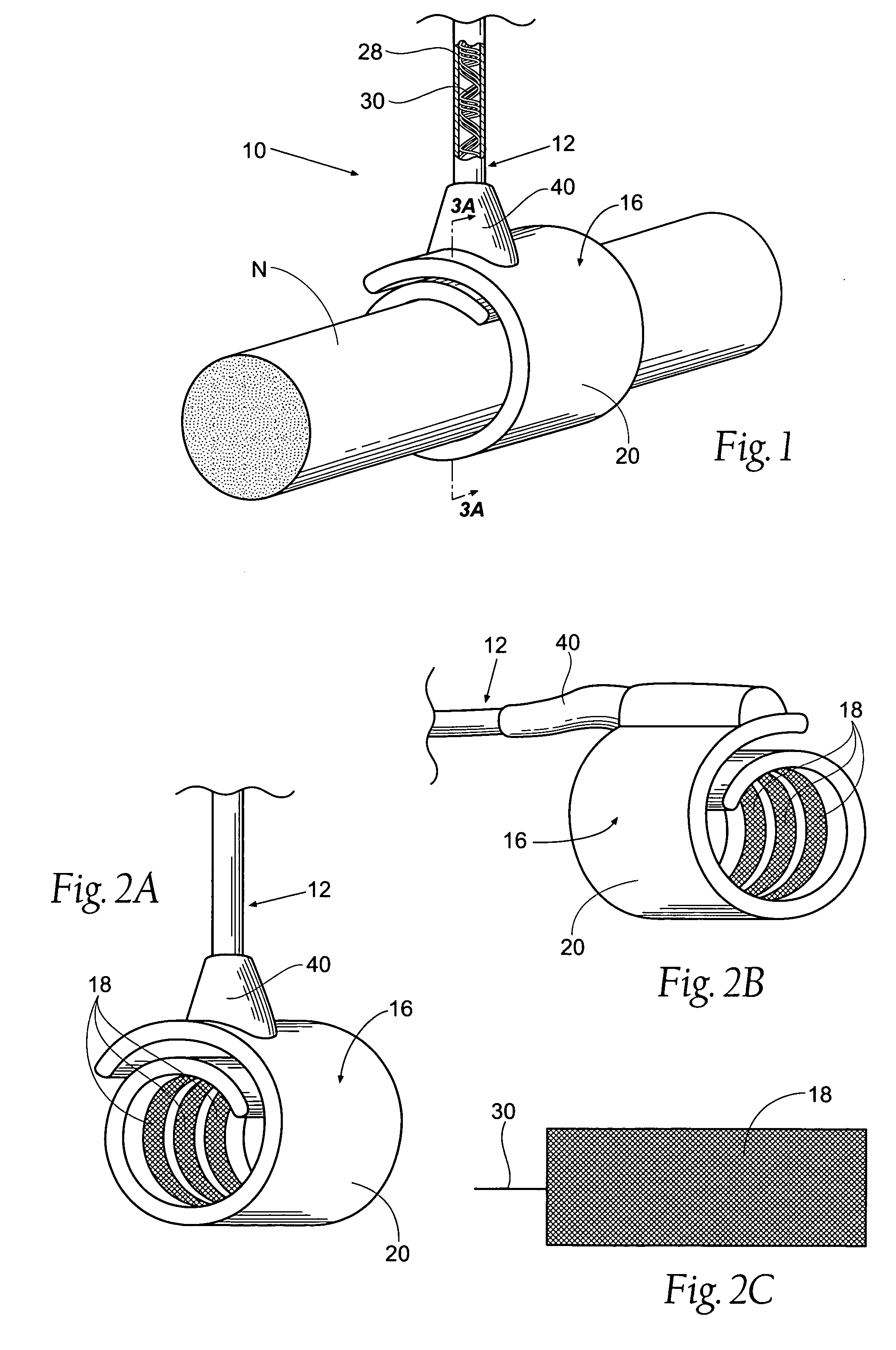
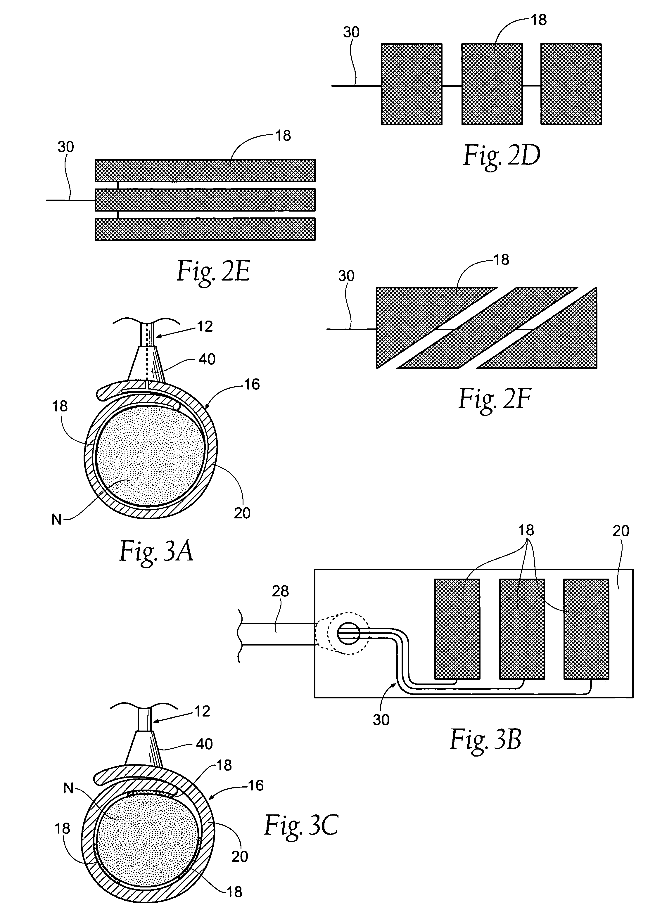
[0033] As FIG. 2A shows, the cuff electrode 16 includes at least one electrically conductive surface 18. In the illustrated embodiment, there are three individually controllable electrically conductive surfaces 18, although more or less may be used. The surface 18 may be solid, as shown in FIG. 2C, or the surface may be segmented into isolated conductive segments electrically coupled by a wire. Alternative embodiments having segmented conductive surfaces 18 are shown in FIGS. 2D through 2F. It is to be appreciated that additional alternative configurations are possible as well.

[0034] In this arrangement, the lead 12 (see FIG. 1) comprises a molded component 28, which encapsulates ...


PUM


Abstract

Devices, systems, and methods for recording, and/or stimulation, and/or blocking of a nerve make use of a molded cuff electrode. An electrically conductive surface is coupled to an inside surface of the cuff's elastic body. The electrically conductive surface and the body assume a coiled configuration in its natural state. An applicator tool having a body and a slider are used to implant the cuff electrode about a nerve.

Description

RELATED APPLICATION [0001] This application claims the benefit of U.S. Provisional Patent Application Ser. No. 60 / 598,695, filed Aug. 4, 2004, and entitled “Devices, Systems, and Methods Employing a Molded Nerve Cuff Electrode” which is incorporated herein by reference.FIELD OF THE INVENTION [0002] This invention relates to nerve cuff electrodes for neuronal recording, stimulation, and blocking in animals, including humans. BACKGROUND OF THE INVENTION [0003] In the last forty years, neuromodulation and neurostimulation implantable technologies have been used extensively for a variety of indications. As such, the components of these systems have developed a significant track record and their actions on the body are reasonably well understood. Many of these systems use implantable pulse generators (IPG's) and electrodes to deliver charge to the site of a biological tissue, i.e., a nerve. By using an appropriate low frequency waveform, the system induces action potentials in a targeted...

Claims


Application Information

Patent Timeline
IPC IPC(8): A61N1/05
CPCA61N1/0556
Inventor MRVA, JOSEPHCOBURN, JAMESSTROTHER, ROBERTTHROPE, GEOFFREY
Owner SPR THERAPEUTICS
Why Eureka
Try Eureka