
Torque detector and method of manufacturing housing of torque detector

a technology of torque detector and manufacturing housing, which is applied in the field of torque detector, can solve the problems of large number of attaching processes that are inconvenient to work, the output of torque detector taken out of the sensor coil through the circuit board is affected by external electromagnetic noise, and the effect of reducing the influence of electromagnetic nois

Inactive Publication Date: 2006-02-16
KOYO SEIKO CO LTD
View PDF12 Cites 0 Cited by
  • Summary
  • Abstract
  • Description
  • Claims
  • Application Information

AI Technical Summary

Benefits of technology

[0012] The present invention is proposed by considering the above-described circumstances. It is an object of the present invention to provide a torque detector in which a sensor part and a circuit board of the torque detector can be easily attached to a housing and the housing can be easily worked for attaching these members, the influence of electromagnetic noise can be reduced under its using state as much as possible and torque can be highly accurately detected, and a method of manufacturing the housing of the torque detector.

Problems solved by technology

In addition thereto, during these operations, an operation for connecting the connecting lead inserted into the lead hole to the circuit board has to be done and a large number of attaching processes are inconveniently required.
Many processes are undesirably required to work them.
Further, the output of the torque detector taken out from the sensor coil through the circuit board is affected by external electromagnetic noise generated in an engine, devices mounted on a vehicle or the like.
Thus, there is a fear that detection accuracy may be possibly deteriorated.

Method used


Image

  • Torque detector and method of manufacturing housing of torque detector
  • Torque detector and method of manufacturing housing of torque detector
  • Torque detector and method of manufacturing housing of torque detector

Examples


Embodiment Construction

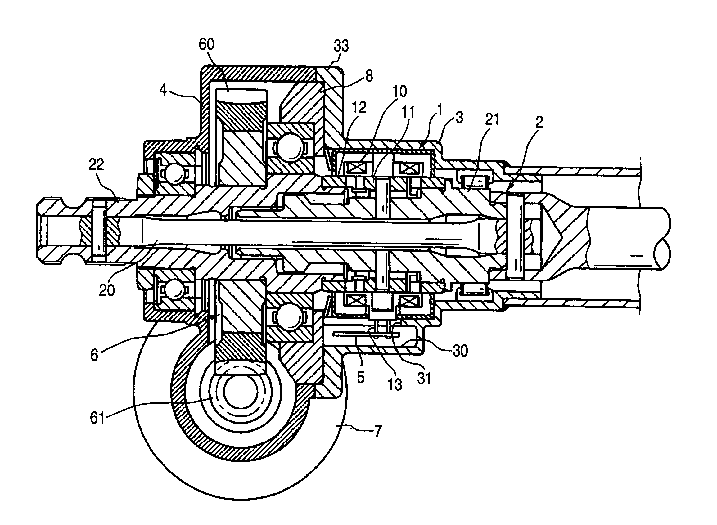
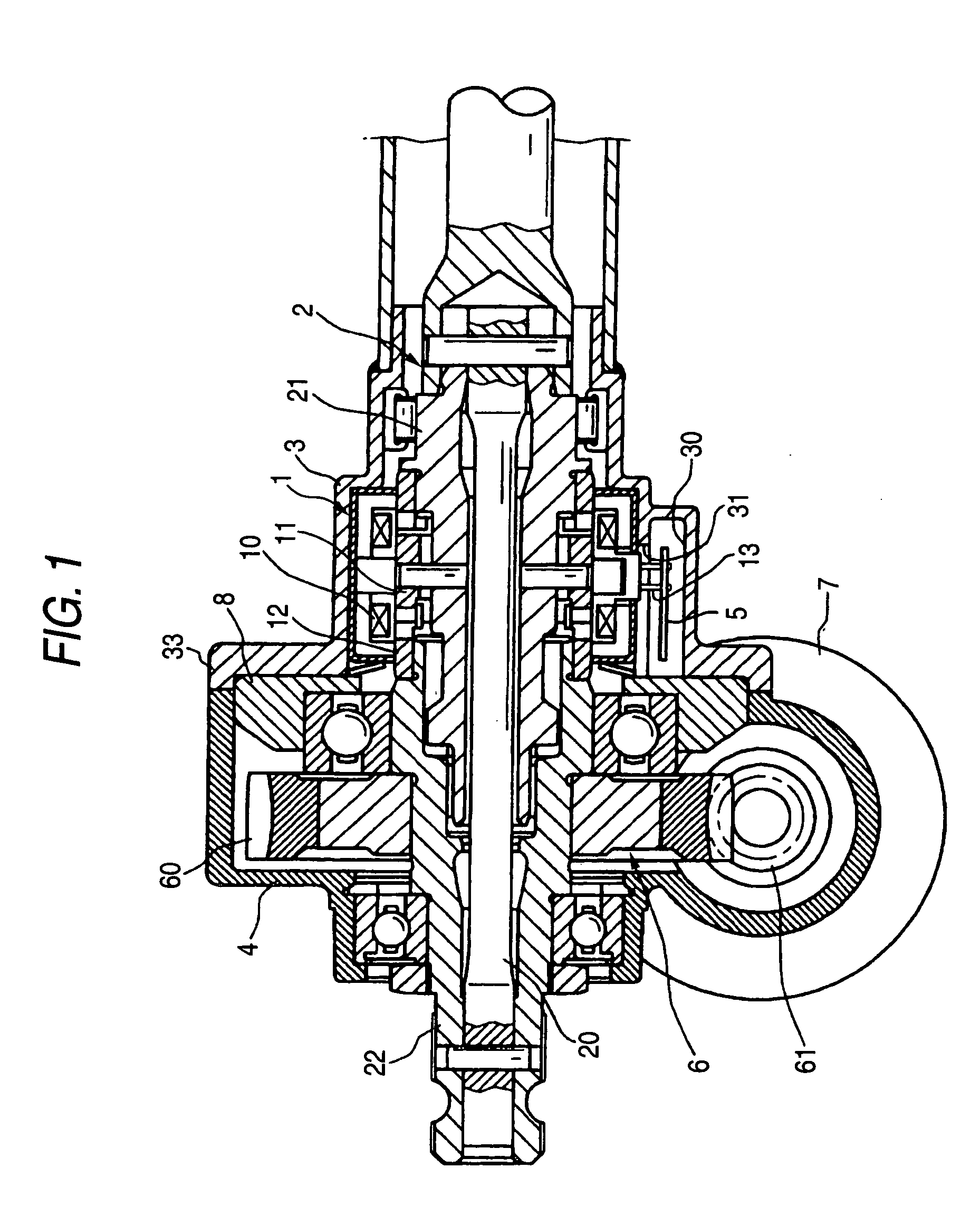
[0031] Now, an embodiment according to the present invention will be described in detail with reference to the drawings. FIG. 1 is a longitudinally sectional view showing the structure of a torque detector according to the present invention. In FIG. 1, an example applied to an electric power steering apparatus is shown. The torque detector 1 is designed to detect a rotating torque exerted on a column shaft (rotating shaft) 2 supported in a tubular sensor housing 3 so as to freely rotate.

[0032] The column shaft 2 is divided into a first shaft 21 and a second shaft 22 connected to each other in a coaxial direction through a torsion bar 20 having a small diameter. The end part of the first shaft 21 protruding to one side of the sensor housing 3 is connected to a steering member not shown. The end part of the second shaft 22 protrudes to the other side of a transmitting housing 4 at the same one side of the sensor housing 3 and is connected to a steering mechanism not shown.

[0033] In ...


PUM

PropertyMeasurementUnit
surface shapeaaaaaaaaaa
torqueaaaaaaaaaa
rotating torqueaaaaaaaaaa

Abstract

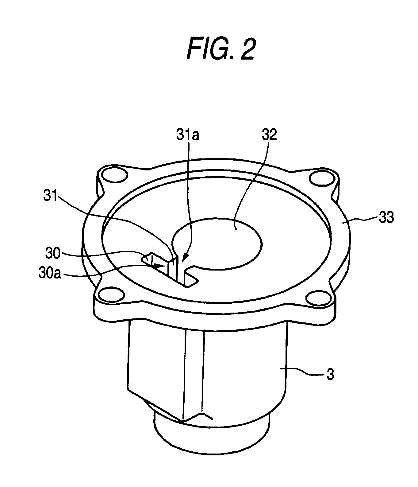
A torque detector includes: a monolithic tubular housing for supporting a rotating shaft, including an opening at one end in a longitudinal direction; a sensor holding hole for holding a sensor part detecting a rotating torque exerted on the rotating shaft, which is provided inside the housing and communicates with the opening; a board chamber for accommodating a circuit board outputting a signal corresponding to the detected rotating torque, which is provided inside the housing and communicates with the opening; a partition wall between the sensor holding hole and the board chamber; and a lead hole passing through the partition wall, into which a lead connecting the sensor part to the circuit board is inserted and which communicates with the opening. The housing is formed by drawing a sheet material in the longitudinal direction.

Description

BACKGROUND OF THE INVENTION [0001] The present invention relates to a torque detector for detecting a rotating torque exerted on a steering member for steering in, for example, an electric power steering apparatus, and a method of manufacturing a housing of the torque detector. [0002] There is an electric power steering apparatus in which a motor for assisting a steering in accordance with the rotating operation of a steering member for steering (for instance, a steering wheel) is driven to transmit the torque of the motor to a steering mechanism and assist the steering. In the power steering apparatus, the rotating torque exerted on the steering member needs to be detected to use the rotating torque for controlling to drive the motor for assisting the steering. For detecting the rotating torque, a torque detector formed halfway a rotating shaft (column shaft) connecting the steering member to the steering mechanism has been hitherto employed. [0003] In the torque detector, the colu...

Claims


Application Information

Patent Timeline
Patent Type & Authority Applications(United States)
IPC IPC(8): G01L1/22B62D5/04B62D6/10G01L3/10G01L5/22
CPCB62D5/0406G01L3/105G01L5/221B62D6/10
Inventor NAKAJIMA, TERUKAZUHIRAKUSHI, SUZO
Owner KOYO SEIKO CO LTD
Learn More