Unlock instant, AI-driven research and patent intelligence for your innovation.

Ratchet wrench with rotating disc

Inactive Publication Date: 2006-02-16
IND TECH RES INST
View PDF8 Cites 4 Cited by
  • Summary
  • Abstract
  • Description
  • Claims
  • Application Information

AI Technical Summary

Benefits of technology

[0006] In another aspect of the present invention, clockwise rotating the rotating disc will inhibit the same clockwise rotation of the ratchet device due to engagement with the ratchet of the handle. Also, a continuou

Problems solved by technology

However, the ratchet wrench is bulky due to the provision of the direction control means at one side of the ratchet device 11.
That is, there is no space available for turning the ratchet device 21 counterclockwise.
As a result, the desired direction switch is not possible.
However, such ratchet wrench also has the problem of inconvenience in use despite its reduced size.

Method used


Image

  • Ratchet wrench with rotating disc
  • Ratchet wrench with rotating disc
  • Ratchet wrench with rotating disc

Examples


Embodiment Construction

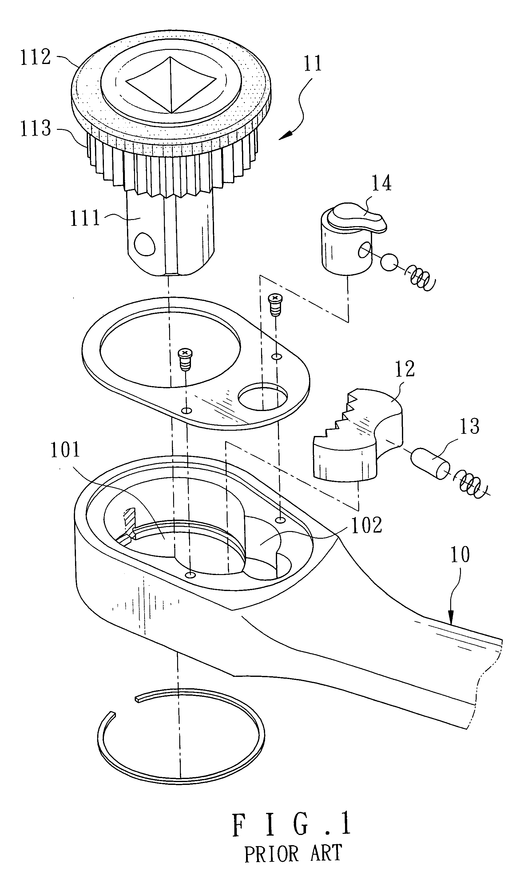
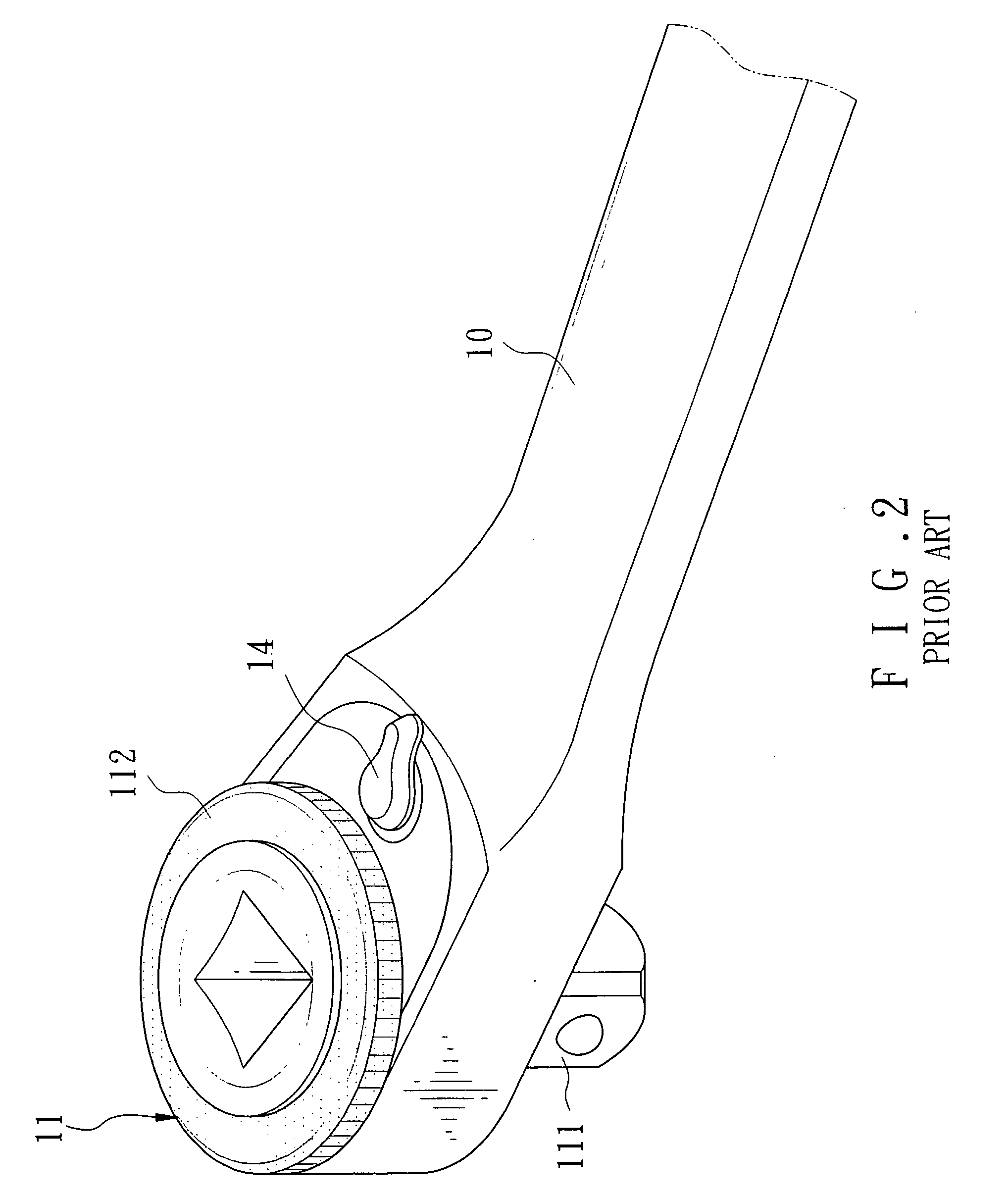
[0022] Referring to FIGS. 7, 8 and 9, there is shown a ratchet wrench constructed in accordance with a preferred embodiment of the invention. As shown, an enclosed box portion 301 having a ratchet 302 around its interior surface is provided at one end of a handle 30. A ratchet device 31 is provided in the box portion 301. The ratchet device 31 comprises a bar 311 extended downwardly, a laterally disposed recess 312 in a main portion thereof, the recess 312 having internal walls 318 and 319, a first bore 313 having a larger diameter in communication with the recess 312, a second bore 314 having a smaller diameter in communication with the first bore 313 and extended downwardly along a center of the bar 311, a spring biased ball 316 provided on a side of the bar 311, a receptacle 317 provided on an interior surface of the first bore 313 and being opposite the recess 312, and a spring 35 and a detent 36 both anchored in the receptacle 317.

[0023] A rotating disc 32 comprises a shaft 32...


PUM


Abstract

A wrench comprises a ratchet device in a ratchet box portion and including a downward bar, a lateral recess having first and second walls, and a bore in communication with the recess; a rotating disc including a shaft extended into the bore, and an actuation member on one side of the shaft; and a locking member in the recess and including an outer ratchet adapted to engage with the ratchet of the handle, an inner groove for receiving and being engaged with the actuation member in the recess, and third and fourth walls at both sides of the groove, either the third or fourth wall being adapted to contact the first or second wall when the locking member pivots to one of left and right positions in the ratchet device. Rotating the rotating disc opposite to the rotation of the handle will switch a direction of exerted force.

Description

FIELD OF THE INVENTION [0001] The present invention relates to wrenches and more particularly to an improved ratchet wrench with a rotating disc. BACKGROUND OF THE INVENTION [0002] A conventional ratchet wrench with a rotating disc is shown in FIGS. 1 and 2. As shown, an enclosed box portion 101 is provided at one end of a handle 10. A ratchet device 11 is provided in the box portion 101. The ratchet device 11 comprises a bar 111 extended downwardly, a top rotating disc 112, and a ratchet wheel 113 provided between the bar 111 and the rotating disc 112. A cavity 102 is provided at an edge of the box portion 101 and in communication therewith. A locking member 12 having a ratchet side is provided in the cavity 102. A spring biased rod 13 at one side opposite the ratchet side of the locking member 12 and a direction switch 14 projected from the box portion 101 are adapted to control the pivoting of the locking member 12 for switching a direction of force exerted upon a workpiece by th...

Claims


Application Information

Patent Timeline
IPC IPC(8): B25B13/46
CPCB25B13/465
Inventor SHU-SUI, LINWAN-CHUAN, LI
Owner IND TECH RES INST
Features
  • R&D
  • Intellectual Property
  • Life Sciences
  • Materials
  • Tech Scout
  • Unparalleled Data Quality
  • Higher Quality Content
  • 60% Fewer Hallucinations
Learn More