Wind flow estimation and tracking using tower dynamics

a tower and wind turbine technology, applied in the field of wind turbines, can solve the problems of insufficient accuracy of the method, inability to accurately measure the average of anemometers installed near the area swept by the blades, and limited effectiveness of the control strategy based on detecting the change in the speed of the rotor

Inactive Publication Date: 2006-02-16
UNITED TECH CORP
View PDF86 Cites 208 Cited by
  • Summary
  • Abstract
  • Description
  • Claims
  • Application Information

AI Technical Summary

Benefits of technology

[0017] The present invention relates to a power generating system in which a turbine is mounted on a support structure held stationary in the horizontal axis with reference to the wind or water flow. The turbine includes a rotor connected to a rotor hub. The rotor has a main blade section with an adjustable pitch angle. The main blade may have an extender blade with an adjusting device connected to the extender blade. A motor moves the extender blade between a retracted position relative to the main blade section to a more extended position to expose more or less of the rotor to the wind.

Problems solved by technology

If this is insufficient, or causes unacceptable power fluctuations, the pitch of the rotor blades is changed to reduce the rotor torque provided by the wind.
Control strategies based on detecting changes in rotor speed are limited in their effectiveness due to the substantial time lag between wind changes and rotor speed changes.
Anemometers installed near to the area swept by the blades cannot accurately measure the average wind speed because they measure wind speed at a single location, whereas wind speed may vary over the area swept by the blades.
Since forces other than the wind influence these parameters, this method is not sufficiently accurate.
No attempt is made to estimate wind flow from tower measurements.

Method used


Image

  • Wind flow estimation and tracking using tower dynamics
  • Wind flow estimation and tracking using tower dynamics
  • Wind flow estimation and tracking using tower dynamics

Examples


Embodiment Construction

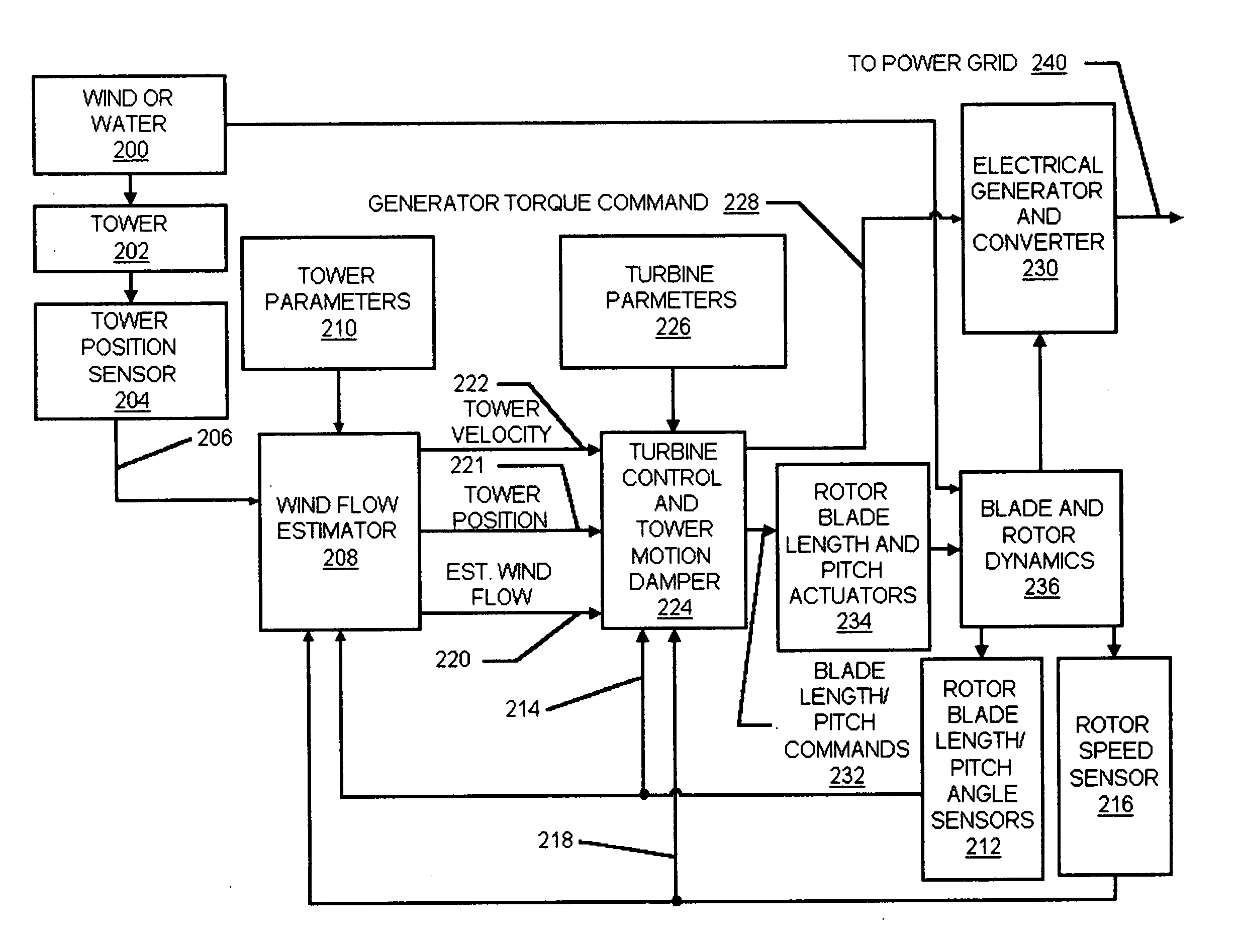
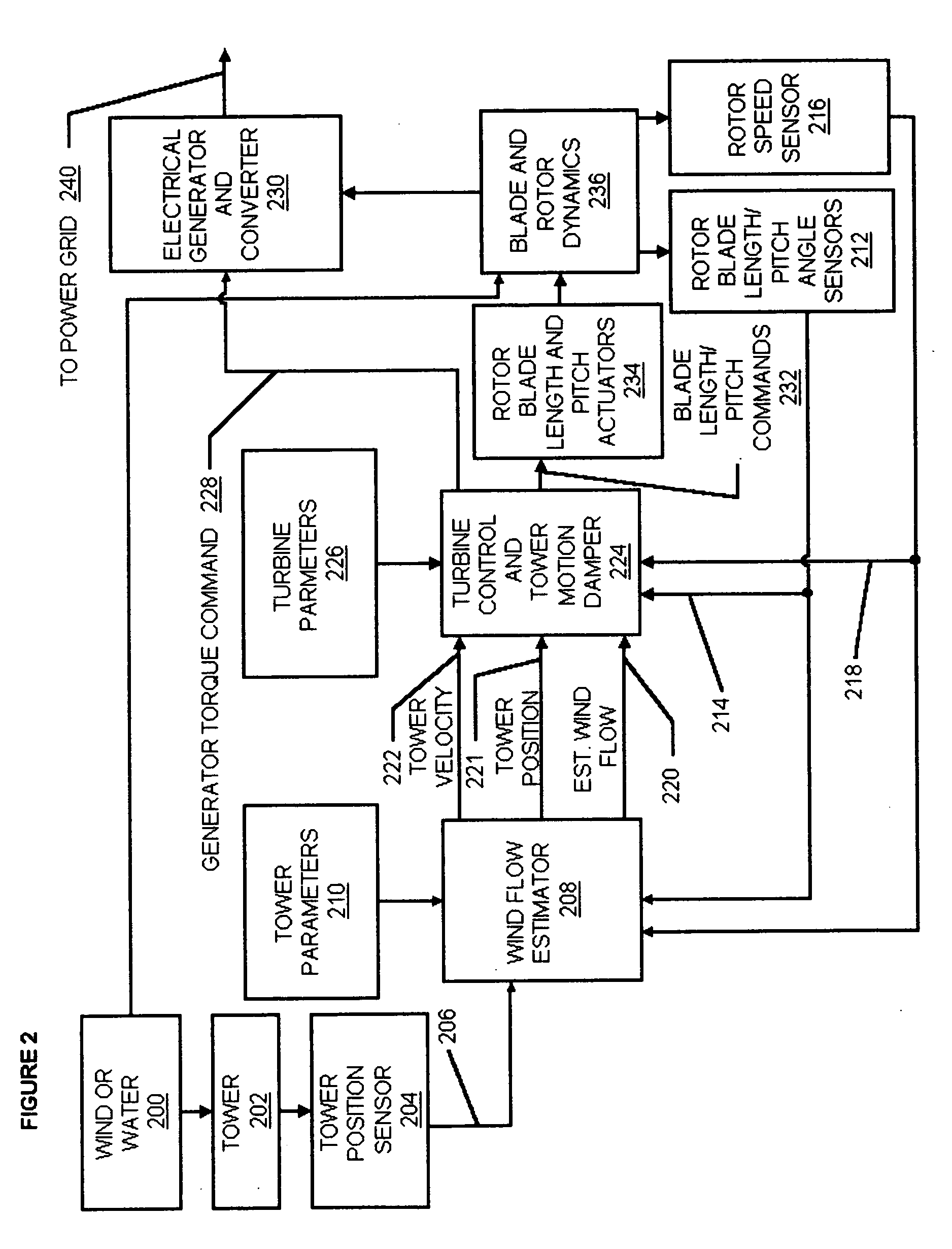
[0030] The invention is described herein with reference to a turbine mounted on a tower and driven by wind flow. The principles of the invention also apply to devices that are tethered and driven and / or buoyed by air or water wherein the support structure is a cable, rod or the like. An example of such devices is disclosed in U.S. Pat. No. 6,091,161 of Dehlsen, et al. granted on Jul. 18, 2000.

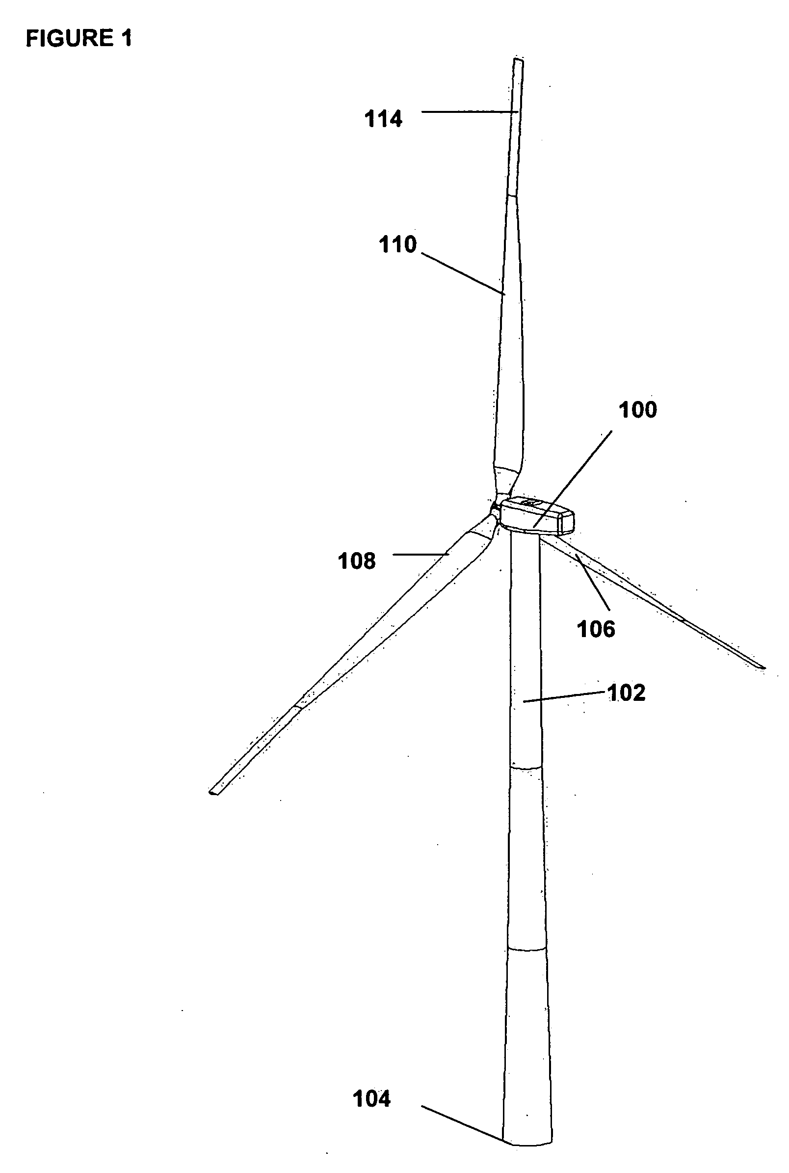
[0031]FIG. 1 illustrates a wind power-generating device. The wind power-generating device includes an electric generator housed in a turbine 100, which is mounted atop a tall tower structure 102 anchored 104 to the ground. The turbine 100 is maintained in the horizontal plane and into the path of prevailing wind current by a yaw control mechanism. The turbine has a rotor with variable pitch blades, 106, 108, 110, which rotate in response to wind. Each blade has a blade base section attached to a rotor shaft that drives the turbine 100 and may have blade pitch angle control capability and / or a ...


PUM


Abstract

A turbine control system for a variable speed electrical generator in a wind turbine mounted atop a support tower. The wind turbine converts wind energy into a driving torque applied to the generator. The control system includes a turbine support tower position sensor and may also include other tower acceleration and velocity sensors. A wind flow estimator uses the measured motion, generator rotation rate and blade pitch angle to predict wind flow over the swept area of the turbine's rotor, and the tower motion. The predicted wind flow and motion is used in the turbine control system to properly adjust its operating point, to tune the controller, to control the rotor rotation rate, and to damp tower oscillations.

Description

CROSS-REFERENCE TO RELATED APPLICATIONS [0001] This application is a Continuation of and claims priority under 35 U.S.C. § 119(e) to U.S. Provisional Patent Application No. 60 / 570,682 “A Wind Speed Estimation And Tracking Using Tower Dynamics”, which was filed on May 11, 2004, and which is incorporated herein by reference.BACKGROUND OF THE INVENTION [0002] 1. Field of the Invention [0003] The present invention relates to wind turbines, and more specifically, to a wind flow estimator for a wind turbine having a rotor driven by wind applying power to turn rotor blades. [0004] 2. Description of Related Art [0005] Most existing wind turbines operate at constant speed. The rotor drives a generator, such as an induction generator, at a constant rotational speed. Constant speed operation is required for a direct link with a constant frequency electrical utility grid. Other more modern wind turbines operate at variable speed to produce DC power, which a converter changes to AC power synchro...

Claims


Application Information

Patent Timeline
Patent Type & Authority Applications(United States)
IPC IPC(8): F03D9/00F01D15/10H02K7/18H02P9/04F03B13/00G05D17/00
CPCF03D1/0608Y02E10/728F03D7/0236F03D7/042F03D11/04F05B2210/16F05B2240/313F05B2260/821F05B2260/96F05B2270/1016F05B2270/32F05B2270/322F05B2270/327F05B2270/332F05B2270/334F05B2270/807Y02E10/721Y02E10/723F03D7/0224F03D13/20F03D9/255Y02E10/72
Inventor WILSON, KITCHENER CLARK
Owner UNITED TECH CORP
Why Eureka
Try Eureka