Prober and probe testing method for temperature-controlling object to be tested

a technology of probes and temperature control objects, applied in the direction of measuring leads/probes, semiconductor/solid-state device testing/measurement, instruments, etc., can solve the problems of high energy consumption of prober, long time for temperature control, and difficulty in controlling the temperature of each object to be tested separately. to achieve the effect of accurate temperature control

Inactive Publication Date: 2006-02-16
TOKYO ELECTRON LTD
View PDF13 Cites 4 Cited by
  • Summary
  • Abstract
  • Description
  • Claims
  • Application Information

AI Technical Summary

Benefits of technology

[0013] It is an object of the present invention according to one aspect of the present application to provide a prober and probing method that can accurately perform temperature control of an object to be tested in a probe test.
[0014] It is an object of the present invention according to another aspect of the present application to provide a prober and probing method that can perform a probing test quickly and efficiently.
[0015] It is an object of the present invention according to still another aspect of the present application to provide a prober that prevents the main chuck from being tilted by a pressure applied by a probe.

Problems solved by technology

It is accordingly difficult to control the temperature of each object to be tested separately.
This prober has a high energy consumption.
This prober also takes a long time for temperature control.

Method used


Image

  • Prober and probe testing method for temperature-controlling object to be tested
  • Prober and probe testing method for temperature-controlling object to be tested
  • Prober and probe testing method for temperature-controlling object to be tested

Examples


first embodiment

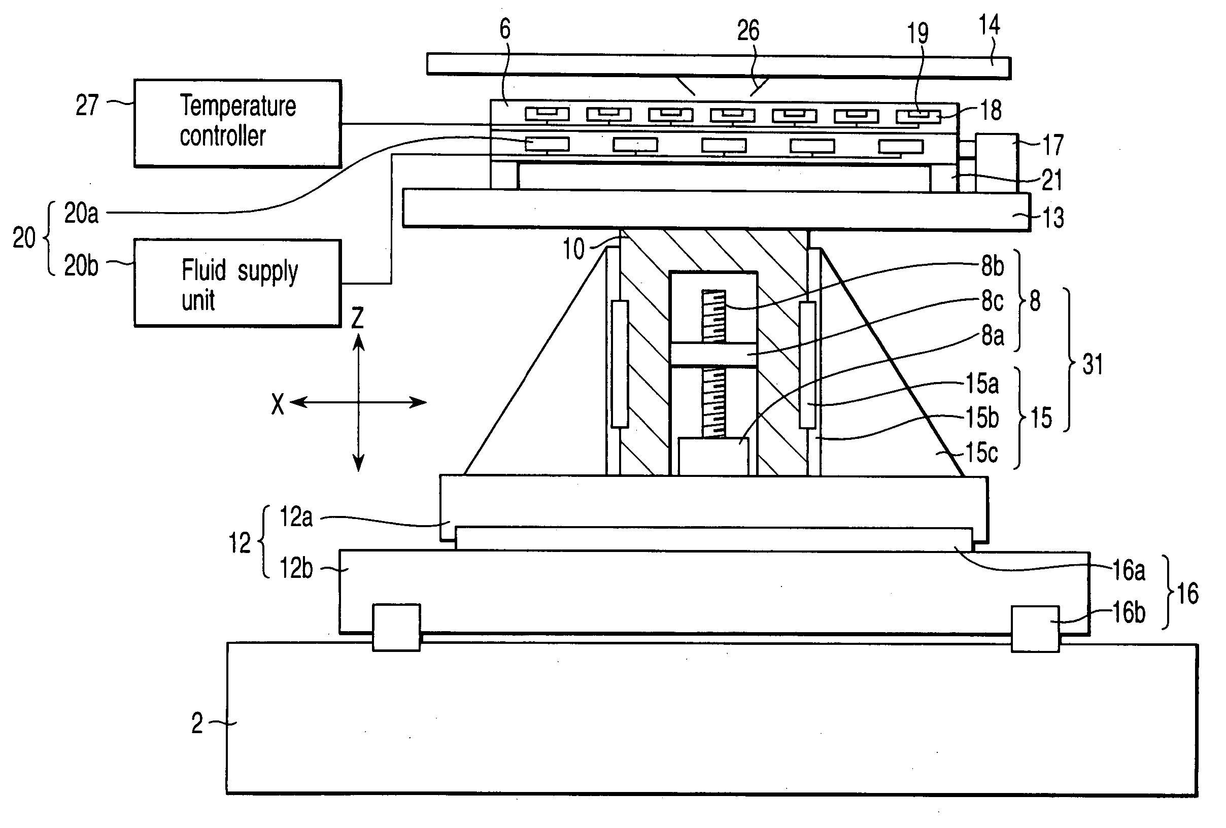
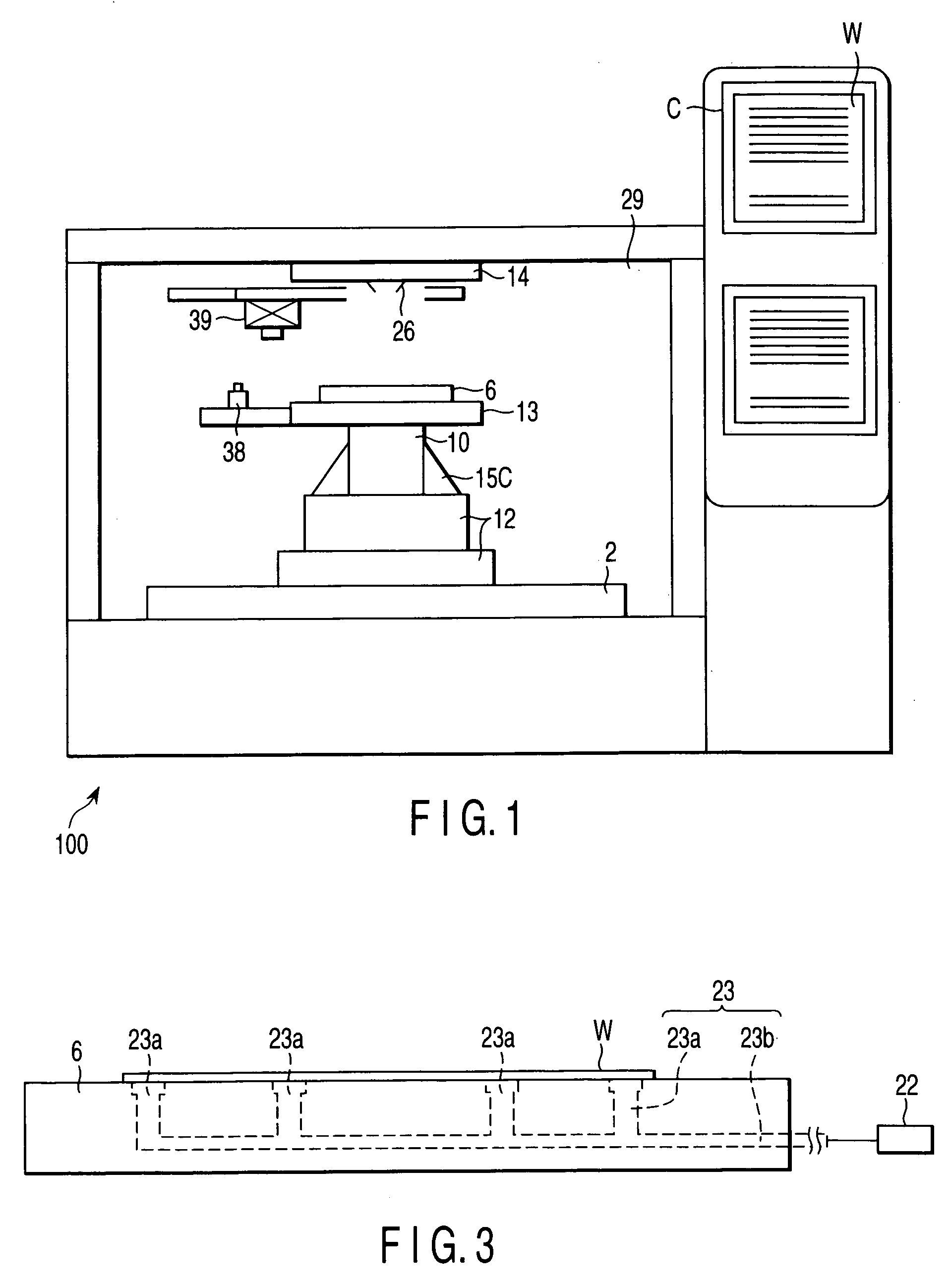
[0059] The embodiments of the present invention will be described with reference to the drawings. FIG. 1 is a sectional view of the main body of a prober 100 according to the present invention. The prober 100 according to this embodiment has a prober chamber 29. A stage base 2 is arranged in the lower portion of the prober chamber 29. An X-Y stage 12, Z stage 10, and main chuck 6 are arrayed on the stage base in the Z direction. A probe card 14 can be arranged in the upper portion of the prober chamber 29 to oppose the main chuck 6. The probe card 14 has a plurality of probes 26. The electrical characteristics of an object to be tested which is placed on the main chuck 6 are tested by using the plurality of probes 26. In the present invention, the X-Y stage is a stage that can move in the X and Y directions. This stage may be a combination of a structure that moves in the X direction and a structure that moves in the Y direction, or may be a single structure that moves in both the X...

third embodiment

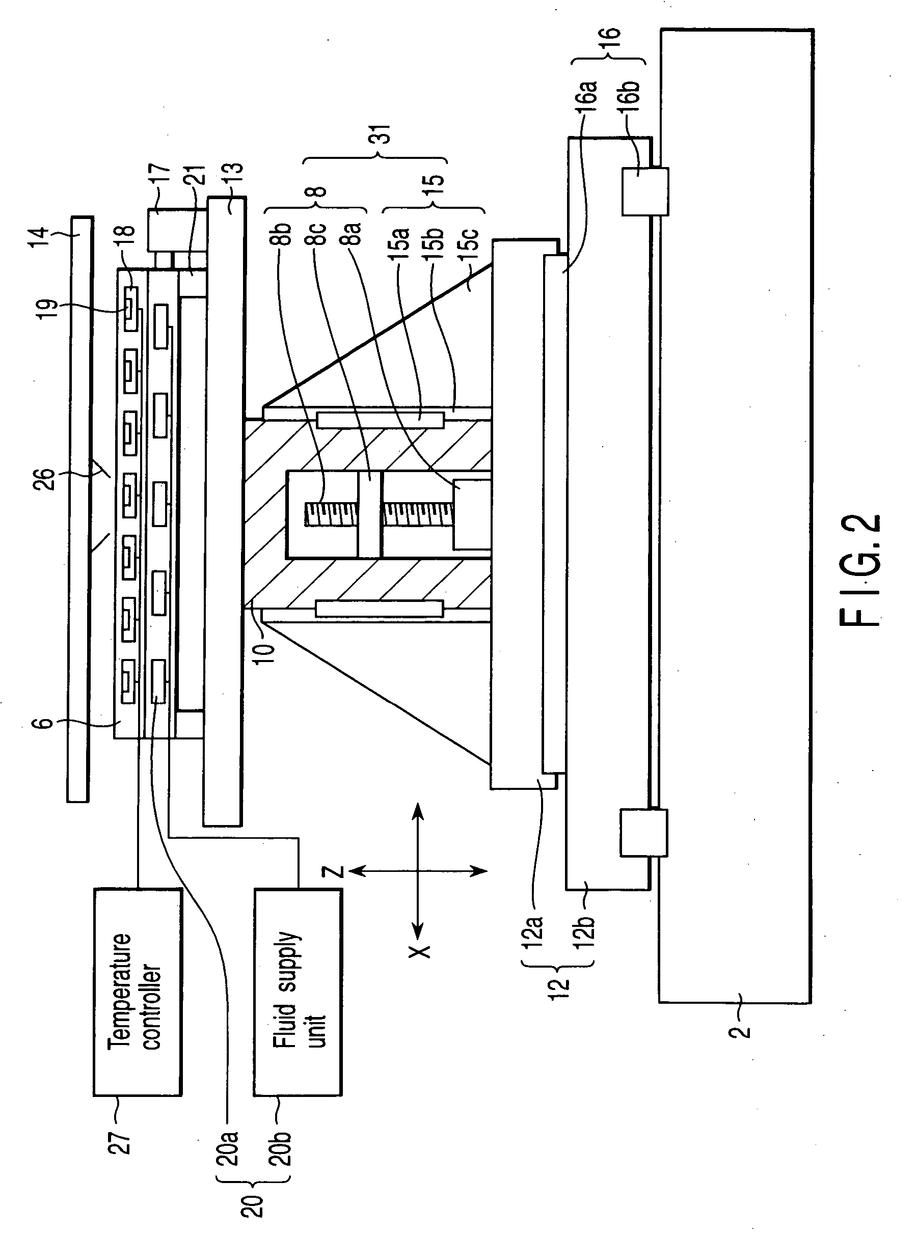
[0080] The operation of the third embodiment will be described. Referring to FIG. 6, the wafer W extracted from a cassette C by a transport mechanism (not shown) is placed on the chuck plate 5 (a). When the chuck plate 5 fixes the wafer, the aligning means described above and the X-Y stage driving mechanism 16 which moves the X-Y stage 12 in the X and Y directions align the object to be tested (b1). At this time, the probing stage 3 and its probing stage elevating mechanism 24 do not move, as they are fixed to the Z stage 10. Subsequently, the rotational driving mechanism 17 cooperates with the aligning mechanism, while rotating the substrate fixing mechanism 23, to determine the position in the θ direction (b2) When the positions in the X, Y, and θ directions are determined, the probing stage 3 is moved upward by the elevating mechanism 24, and the upper flat surface of the probing stage 3 comes into contact with the bottom surface of the wafer W (c). A Z stage elevating mechanism ...

second embodiment

[0084] The heater 18 provided to the probing stage 3 can include one or a plurality of heaters 18. When a plurality of heaters are provided, they can have cell structures 9 in the same manner as in the Both the temperature sensor 19 and heat exchanger 20 can be provided in the same numbers as that of the heaters 18. The upper flat surface of the probing stage 3 preferably has a size substantially the same as that of one object to be tested or a group of the plurality of objects to be tested that are to be tested at once. With this arrangement, the temperature of only the object which is to be tested can be controlled, and the time required for increasing the temperature of the object to be tested can be shortened. Also, energy consumption and loss can be decreased.

[0085] The probing stage 3 can be made of a metal having high thermal conductivity such as aluminum, and is detachably attached to a probing stage elevating mechanism. Accordingly, the probing stage 3 can be exchanged for...


PUM


Abstract

A prober which tests an object to be tested under temperature control is provided. This prober includes a stage base, Z stage, X-Y stage having a frame structure, substrate fixing mechanism arranged on the X-Y stage, a probe card arranged to oppose the substrate fixing mechanism, and a probing stage fixed on the Z stage and arranged in the frame structure of the X-Y stage such that its axis coincides with an extension line vertically extending from the probe center of the probe card. The probing stage includes a probing elevating mechanism, and a temperature controller to heat and cool the object to be tested. The probing stage supports the substrate of the object to be tested from the bottom surface, and controls the temperature of the object to be tested.

Description

CROSS-REFERENCE TO RELATED APPLICATIONS [0001] This is a Continuation Application of PCT Application No. PCT / JP03 / 09457, filed Jul. 25, 2003, which was not published under PCT Article 21(2) in English.[0002] This application is based upon and claims the benefit of priority from prior Japanese Patent Application No. 2002-305925, filed Oct. 21, 2002, the entire contents of which are incorporated herein by reference. BACKGROUND OF THE INVENTION [0003] 1. Field of the Invention [0004] The present invention relates to a prober and probe testing method which test an object to be tested generally arranged on a wafer-like substrate under temperature control and, more particularly, to a prober and probe testing method that test the electrical characteristics of an object to be tested more accurately. [0005] 2. Description of the Related Art [0006] When the electrical characteristics of an integrated circuit, a liquid crystal display, or the like arranged on a wafer-like substrate (to be refe...

Claims


Application Information

Patent Timeline
Patent Type & Authority Applications(United States)
IPC IPC(8): G01R31/02G01R1/06G01R1/067G01R31/28H01L21/66
CPCG01R1/06705G01R31/2891G01R31/2874G01R31/2865G01R1/06G01R31/28H01L22/00
Inventor SUGIYAMA, MASAHIKOINOUE, YOSHINORI
Owner TOKYO ELECTRON LTD
Why Eureka
Try Eureka