Light emitting diode lens and backlight apparatus having the same

a technology of led array modules and backlight apparatus, applied in the field of lenses, can solve problems such as uncontrollable vertical direction of light beams, and achieve the effect of reducing the number of led array modules

Active Publication Date: 2006-02-16
SAMSUNG ELECTRONICS CO LTD
View PDF4 Cites 70 Cited by
  • Summary
  • Abstract
  • Description
  • Claims
  • Application Information

AI Technical Summary

Benefits of technology

[0012] It is another object of the present invention to provide an LED lens which

Problems solved by technology

There is a problem in that some of the light beams maybe uncontrollably d

Method used


Image

  • Light emitting diode lens and backlight apparatus having the same
  • Light emitting diode lens and backlight apparatus having the same
  • Light emitting diode lens and backlight apparatus having the same

Examples


first embodiment

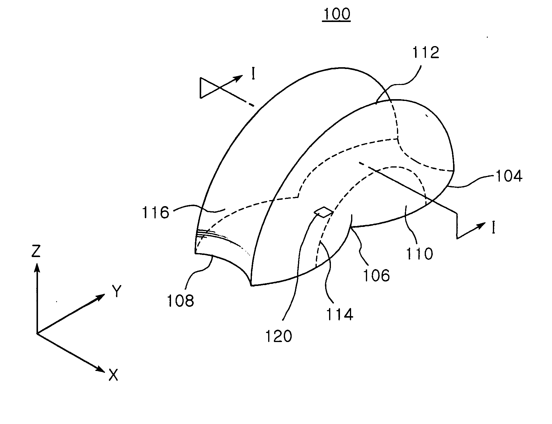
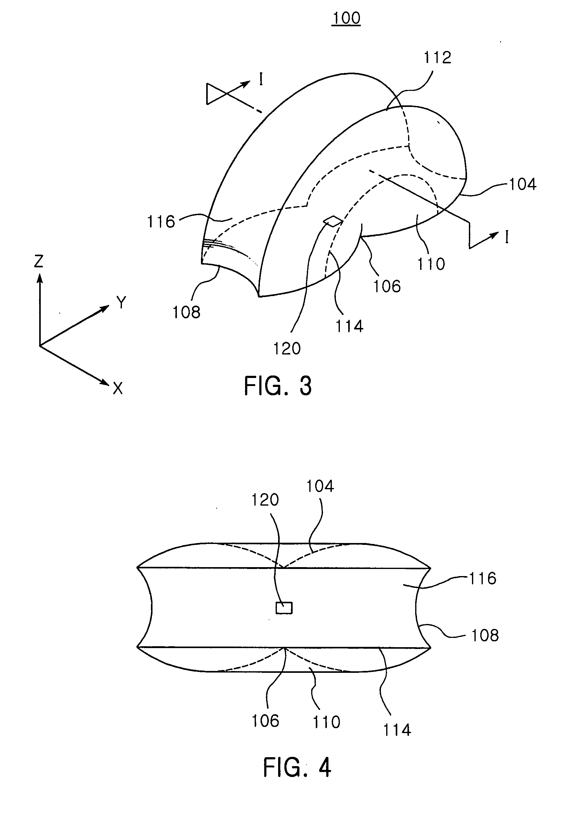
[0051] FIGS. 3 to 8 illustrate the structure of an LED lens according to a first embodiment of the present invention, in which FIG. 3 is a perspective view of an LED lens according to a first embodiment of the present invention, FIG. 4 is a plan view of the LED lens shown in FIG. 3, FIG. 5 is a side elevation view of the LED lens shown in FIG. 3, FIG. 6 is a front elevation view of the LED lens shown in FIG. 3, FIG. 7 is a bottom view of the LED lens shown in FIG. 3, and FIG. 8 is a cross-sectional view of the LED lens shown in FIG. 3 taken along the line I-I.

[0052] Referring to FIGS. 3 to 8, an LED lens 100 according to the first embodiment of the present invention is made of transparent material, and so configured to radiate light from an underlying LED chip 120 in a specific beam angle to the outside.

[0053] The LED lens 100 of this embodiment has a peanut-shaped planar bottom 102, a pair of reflecting surfaces 110 extended upward from the bottom 102 and a radiating surface 116 ...

second embodiment

[0078] FIGS. 15 to 20 illustrate the structure of an LED lens according to a second embodiment of the present invention, in which FIG. 15 is a perspective view of the LED lens according to the second embodiment of the present invention, FIG. 16 is a plan view of the LED lens shown in FIG. 15, FIG. 17 is a front elevation view of the LED lens shown in FIG. 15, FIG. 18 is a side elevation view of the LED lens shown in FIG. 15, FIG. 19 is a bottom view of the LED lens shown in FIG. 15, and FIG. 20 is a cross-sectional view of the LED lens shown in FIG. 15 taken along the line II-II.

[0079] Referring to FIGS. 15 to 20, an LED lens 200 according to the second embodiment of the present invention is made of transparent material, and so configured to radiate light from an LED chip 220, which is placed in the bottom thereof, in a specific beam angle to the outside.

[0080] The LED lens 200 of this embodiment includes a planar bottom 202 in the form of opposed crowns, a pair of first and secon...


PUM


Abstract

The present invention relates to an LED lens, in which a planar bottom has a pair of halves symmetrically connected with each other about a reference line and narrowed in the vicinity of the reference line. A pair of substantially semicircular reflecting surfaces are extended from both edges of the bottom connected with both ends of the reference line. A radiating surface is connected with remaining edges of the bottom and semicircular edges of the reflecting surfaces. The reflecting surfaces reflect light beams are introduced from the LED chip through the bottom toward the radiating surface. The radiating surface radiates the light beams to the outside when the light beams are introduced to the radiating surface through reflection from the reflecting surfaces and directly through the bottom, so that the light beams are radiated to the outside in a predetermined beam angle.

Description

RELATED APPLICATION [0001] The present application is based on, and claims priority from, Korean Application Number 2004-6321, filed Aug. 11, 2004, the disclosure of which is hereby incorporated by reference herein in its entirety. BACKGROUND OF THE INVENTION [0002] 1. Field of the Invention [0003] The present invention relates to a lens, and more particularly, to a Light Emitting Diode (LED) lens for radiating light from an LED chip in a predetermined beam angle to the outside and a backlight apparatus incorporating the same. [0004] 2. Description of the Related Art [0005] A Liquid Crystal Display (LCD) is gaining attention as a next generation display according to the development of the electronic industry. The LCD is generally equipped with a backlight apparatus for illuminating an LCD panel from behind since the LCD panel does not light spontaneously. [0006]FIG. 1 is a cross-sectional view illustrating a conventional LED which is proposed in U.S. Pat. No. 6,679,621 as a light so...

Claims


Application Information

Patent Timeline
IPC IPC(8): F21V7/04H01L33/58F21V7/00G02F1/133H01L33/60
CPCH01L33/58H01L33/54H01L33/60G02F1/1335
Inventor HAHM, HUN JOOPARK, JUNG KYUJEONG, YOUNG JUNEPARK, YOUNG SAMKIM, HYUNG SUKAHN, HO SIK
Owner SAMSUNG ELECTRONICS CO LTD
Why Eureka
Try Eureka