
Jet blast resistant vehicle arresting blocks, beds and methods

a technology for arresting blocks and vehicles, applied in the direction of shock absorbers, ways, elastic dampers, etc., can solve the problems of limiting the useful life of arresting beds, limited strength to permit compressive failure of concrete, and material such as cellular concrete, so as to reduce the transmission of external phenomena

Inactive Publication Date: 2006-02-16
RUNWAY SAFE IPR AB
View PDF16 Cites 3 Cited by
  • Summary
  • Abstract
  • Description
  • Claims
  • Application Information

AI Technical Summary

Benefits of technology

The solution provides improved resistance to jet blast and other external forces, enhancing the durability and longevity of the arresting unit while maintaining the necessary compressive failure characteristics for safe aircraft arrestment.

Problems solved by technology

However, in some applications, depending in part upon particular airport layout, the proximity of jet blast or other physical forces may give rise to deteriorating or destructive effects which could limit the useful life of an arresting bed.
Material such as cellular concrete, when used in an arresting bed, must have limited strength to permit compressive failure of the concrete without destruction of the landing gear of an aircraft, for example.
Thus, the requirement to limit the strength of compressible material used for arresting purposes, in turn may make the material susceptible to damage or destruction by sonic, pressure, vibrational, lift, projected gravel and other characteristics and effects of jet blast from nearby aircraft, as well as from other sources, such as objects, people or vehicles making contact with an arresting bed other than during actual arresting incidents.

Method used


Image

  • Jet blast resistant vehicle arresting blocks, beds and methods
  • Jet blast resistant vehicle arresting blocks, beds and methods
  • Jet blast resistant vehicle arresting blocks, beds and methods

Examples


Embodiment Construction

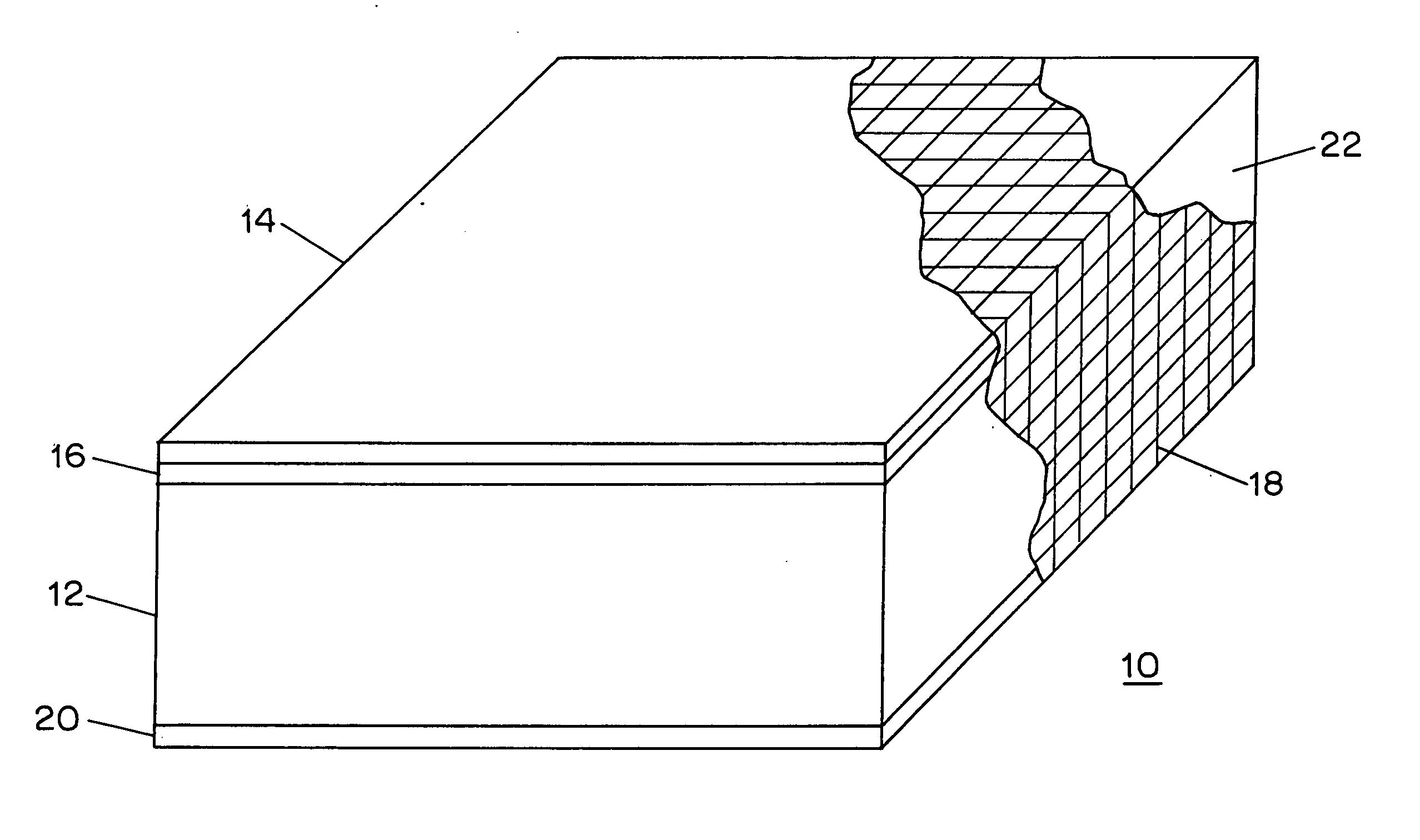
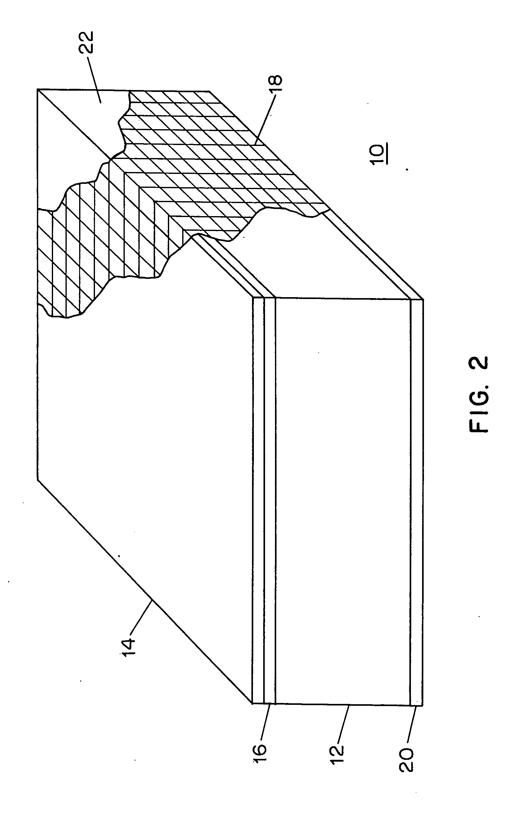
[0027]FIG. 2 illustrates an embodiment of a vehicle arresting unit 10 pursuant to the invention. The drawing is not necessarily to scale and may represent an arresting unit of dimensions four feet by four feet by six to thirty inches thick, for example.

[0028] As shown, vehicle arresting unit 10 includes a block of compressible material 12, having top, bottom and side surfaces and a top to bottom thickness. Block 12 may be cellular concrete fabricated in accordance with the '068 patent or otherwise, or may be formed of phenolic foam, ceramic foam, or other suitable material. As described in the '025 patent, for aircraft arresting applications suitable arresting material characteristics are selected to enable aircraft travel to be arrested within a desired distance, without causing passenger injury or aircraft damage such as landing gear failure. For example, cellular concrete fabricated so as to provide a compressive gradient strength ranging between 60 to 80 psi (pounds per square ...


PUM


Abstract

Aircraft arresting beds constructed of cellular concrete at ends of runways may be subject to damaging effects of jet blast phenomena. Arresting units resistant to such effects and related methods are described. A block of compressible material, such as cellular concrete, provides compressive failure characteristics suitable for arresting travel of an aircraft overrunning a runway. Relatively thin frangible material positioned above the block provides a stronger, more damage resistant surface, while still readily fracturing in an arresting incident. Intermediate material, such as a foam layer, positioned under the frangible material may be included to provide a protective cushioning effect by mitigating transmission of external phenomena forces to the block. A fastening configuration at least partially enclosing other portions of the arresting unit provides a stable unified composite, without destroying desired compressive failure characteristics of the unit. Arresting units may also include a bottom layer of material stronger than the block of compressible material and a sealant coating with water resistant properties.

Description

RELATED APPLICATIONS [0001] This application is a continuation application of prior application Ser. No. 10 / 755,163, filed Jan. 9, 2004, which is a divisional application of prior application Ser. No. 09 / 951,080, filed Sep. 13, 2001.FEDERALLY SPONSORED RESEARCH [0002] (Not Applicable) BACKGROUND OF THE INVENTION [0003] This invention relates to arresting the forward motion of vehicles, such as aircraft overrunning a runway, and more particularly to arresting embodiments with improved resistance to jet blast and other potentially destructive forces. [0004] The problem of aircraft overrunning the ends of runways, with the possibility of passenger injury and aircraft damage, is discussed in U.S. Pat. No. 5,885,025, “VEHICLE ARRESTING BED SYSTEMS” (which may be referred to as “the '025 patent”). That patent, together with U.S. Pat. No. 5,902,068, “VEHICLE ARRESTING UNIT FABRICATION METHOD” (the '068 patent) and U.S. Pat. No. 5,789,681, “ARRESTING MATERIAL TEST APPARATUS AND METHODS” (th...

Claims


Application Information

Patent Timeline
Patent Type & Authority Applications(United States)
IPC IPC(8): E01C7/00B64F1/02E01C9/00
CPCB64F1/025B64F1/02E01C9/007
Inventor ALLEN, GLENNANGLEY, RICHARD D.GORDON, JOHN L.MAHAL, PETER T.VALENTINI, SILVIA C.
Owner RUNWAY SAFE IPR AB
Learn More