Mold assembly with closure mechanism

a technology of a closure mechanism and a moulding assembly, which is applied in the field of mould assembly, can solve problems such as inaccuracy in closing, and achieve the effect of facilitating the demoulding of glued articles

Active Publication Date: 2006-02-16
LM GLASSFIBER
View PDF9 Cites 41 Cited by
  • Summary
  • Abstract
  • Description
  • Claims
  • Application Information

AI Technical Summary

Benefits of technology

[0005] The object of the invention is to provide a mould assembly allowing a simple, fast and accurate closure and opening of the mould parts. A further object is to improve the demoulding process.
[0006] According to the invention, the assembly is characterised in that the displacement means are formed of protractile guide rods mounted on one of the two mould parts along the two longitudinal sides thereof extending substantially parallel to the hinge line and associated bearing means provided on the longitudinal sides of the other mould part for receiving the free ends of the guide rods such that the second mould part may rest on the guide rods in the second position of the mould, the guide rods including drive means for displacing the guide rods and thus moving the two mould parts between the second and third positions of the mould. A very accurate closing of the two mould parts is thereby obtained in a rectilinear movement. When operating with large mould parts, which are closed exclusively by means of a hinge mechanism, the dead load of the mould parts causes heavy torques and thus elastic deformations, which in turn result in slack and an inaccurate closing, unless the mould parts and the hinge mechanism are disproportionately heavily dimensioned. According to the invention this drawback is avoided by means of the protractile guide rods and the associated bearings arranged along the two longitudinal sides. Furthermore the risk of so-called “overbite” or “reversed overbite” of the two mould parts in the areas, where the outer edges are not placed precisely opposite each other, is significantly reduced.

Problems solved by technology

When operating with large mould parts, which are closed exclusively by means of a hinge mechanism, the dead load of the mould parts causes heavy torques and thus elastic deformations, which in turn result in slack and an inaccurate closing, unless the mould parts and the hinge mechanism are disproportionately heavily dimensioned.

Method used


Image

  • Mold assembly with closure mechanism
  • Mold assembly with closure mechanism
  • Mold assembly with closure mechanism

Examples


Embodiment Construction

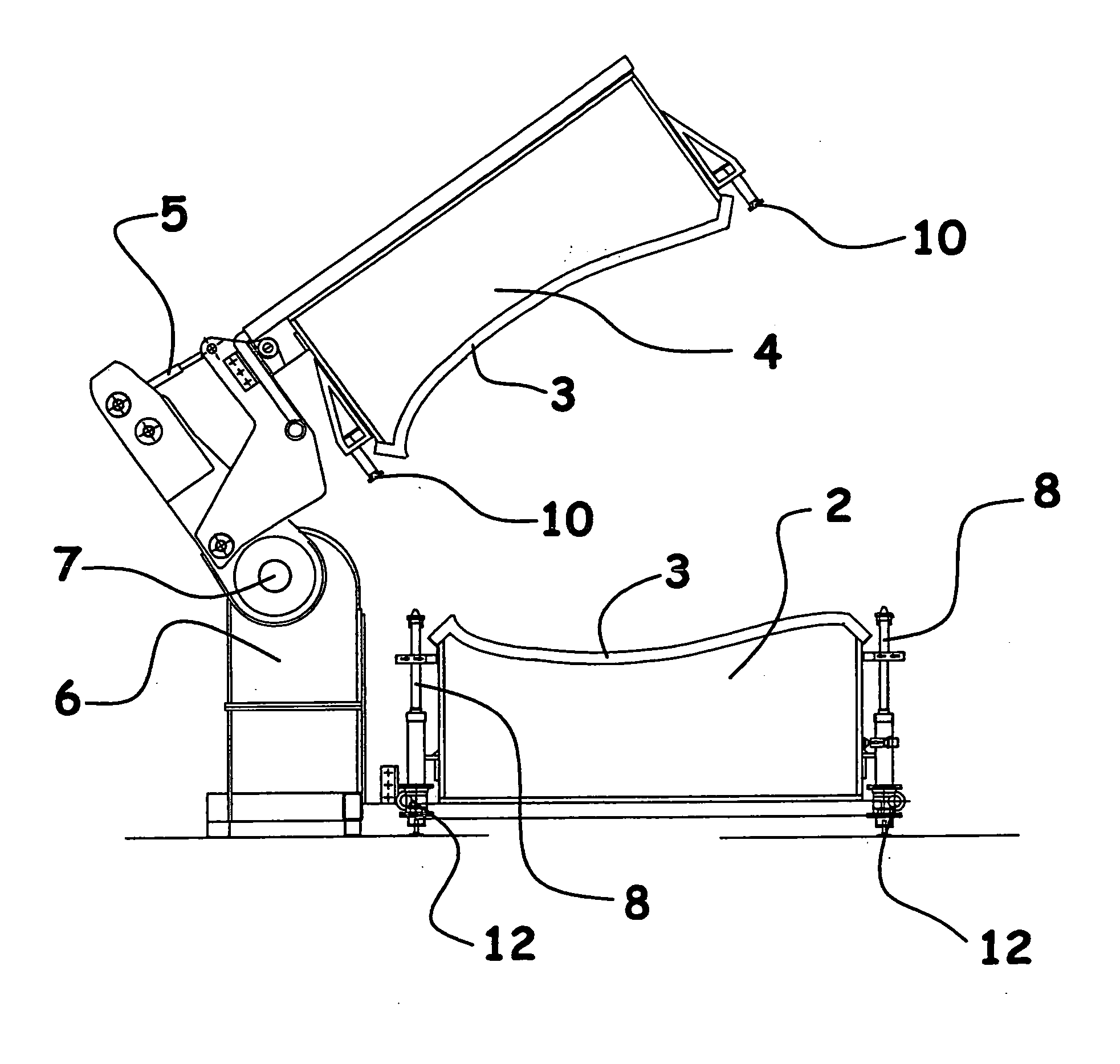
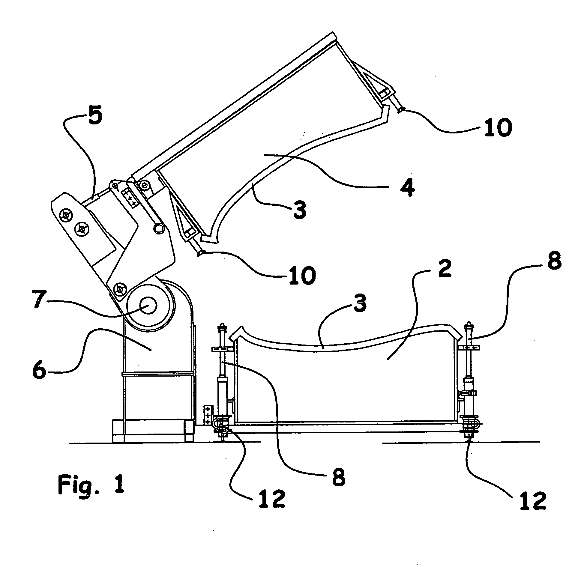
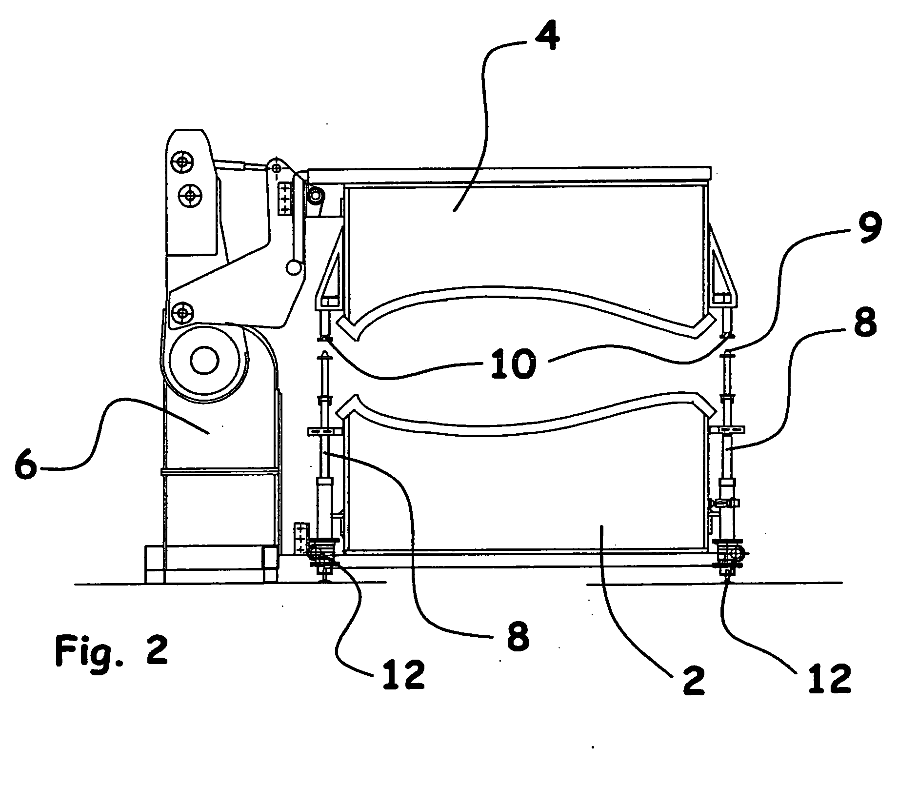
[0026] The mould assembly according to the invention is particularly suitable for producing a wind turbine blade, which is made by moulding two blade shell halves in separate mould parts and subsequently gluing the blade shell halves together. The blade shell halves per se are typically made by vacuum infusion, in which evenly distributed fibres, rovings, which are fibre bundles, bands of rovings or mats, which may be felt mats of single-fibres or woven mats of fibre rovings, are layered in a mould part and covered by a vacuum bag. By creating vacuum in the cavity between the inner face of the mould part and the vacuum bag, fluid polymer may be sucked into and fill the cavity containing the fibre material. When the polymer has cured, the vacuum bag is removed, and the two blade shell halves may be glued together along the edges and by means of one or more bracings extending in the longitudinal direction of the blade between the inner faces of the two blade shell halves. The joining ...


PUM

PropertyMeasurementUnit
distanceaaaaaaaaaa
lengthaaaaaaaaaa
displacementaaaaaaaaaa

Abstract

Mould assembly including a first mould part (2) and a second mould part (4) for moulding a substantially elongated, closed profile member, in particular a wind turbine blade of fibre-reinforced polymer, said mould assembly including a hinge mechanism (6) with a hinge line (7) extending parallel to the two mould parts in the longitudinal direction of the mould to allow turning of the mould parts in relation to each other between an open position and a closed position. The mould assembly includes displacement means for a rectilinear translational movement of the second mould part (4) between a partially closed position and a completely closed position. The displacement means are formed of guide rods (8) including drive means for displacing the guide rods (8) and thus for moving the two mould parts between the partially closed and completely closed positions. The invention further relates to a method of using the mould assembly.

Description

TECHNICAL FIELD [0001] The invention relates to a mould assembly according to the preamble to claim 1 and the use of such a mould assembly. BACKGROUND ART [0002] It is commonly known that moulds for making large articles such as wind turbine blades and consisting of two mould parts are closed about a longitudinal hinge line, where the hinges are passive, ie a crane is used to lift one of the mould parts about the hinge line for closure and opening of the mould. When making wind turbine blades, the mould is closed so as to glue two blade shell halves together, said shell halves being produced in separate mould parts. [0003] Danish patent application No DK 2000 01281 discloses an assembly according to the preamble to claim 1, a drive unit built into the hinge structure lifting and turning a mould part from a position, in which its opening faces upwards, to a position above the other mould part, in which the openings of the two mould parts face each other. The closure mechanism include...

Claims


Application Information

Patent Timeline
Patent Type & Authority Applications(United States)
IPC IPC(8): B28B1/00B29C33/26B29C69/00B29C70/44F03D1/06
CPCB29C33/26B29C69/004B29C70/443Y02E10/721F03D1/065F05B2240/30B29L2031/08B29L2031/085Y02E10/72Y02P70/50
Inventor OLSEN, SOREN MALCHOJENSEN, FREDDIE REYMONDKLINDT, PETERLIEBMANN, AXEL
Owner LM GLASSFIBER
Why Eureka
Try Eureka