

Milling machine
- Summary
- Abstract
- Description
- Claims
- Application Information
AI Technical Summary
Benefits of technology
Problems solved by technology
Method used
Image

Examples
Example
DETAILED DESCRIPTION OF THE DRAWINGS
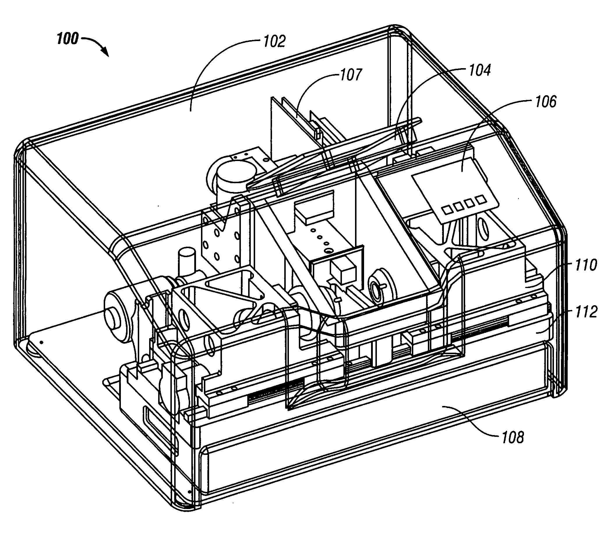
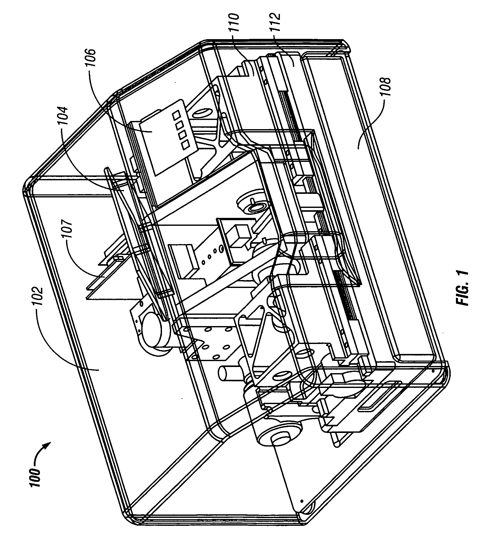
[0023] This inventive milling machine is sized to fit on the countertop of a dentist office or in a lab. Its generally compact size however does not mean that the quality of end product is diminished. Instead, the milling machine is built so robustly that it will produce the highest quality crowns and inlays. An intra-oral digitizer is used to measure the dimensions of the prepared tooth, as well as the adjacent and opposed teeth. Software within the digitizer constructs an outer contour that meshes with the adjacent and opposing teeth. The design is approved by the dentist and then conveyed to the milling machine.
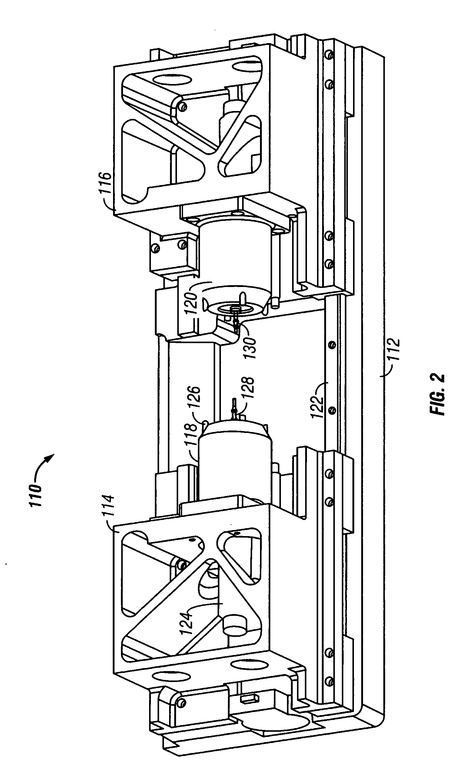
[0024]FIGS. 1 and 2 provide perspective views of the milling machine 100. It includes a cover 102 that protects the operator from the moving parts within. A blank 10 is held within a work area that is accessible through door 104. The x-axis carriage 110 is used to move the tools back and forth into engagement with the blank 10. The car...
PUM
| Property | Measurement | Unit |
|---|---|---|
| Color | aaaaa | aaaaa |
| Perimeter | aaaaa | aaaaa |
Abstract
Description
Claims
Application Information