Tibial spacer blocks and femoral cutting guide

a technology of femoral cutting guide and femoral spacer, which is applied in the field of femoral cutting guide and tibial spacer block, can solve the problems of not providing an associated, attachable device for intramedullary femoral resection guid

Active Publication Date: 2006-02-16
SMITH & NEPHEW INC
View PDF99 Cites 119 Cited by
  • Summary
  • Abstract
  • Description
  • Claims
  • Application Information

AI Technical Summary

Benefits of technology

[0005] In one embodiment, the present invention includes a spacer block, or a plurality of blocks of different thicknesses, that are configured to be temporarily positioned upon a resected proximal portion of a tibia, where the spacer block essentially mimics the shape, in the thickness direction (i.e., the distal/proximal direction), of the tibial component of the knee joint prosthesis intended to be implanted. The spacer block can then be used when performing a range of motion analysis, and to check the fl...

Problems solved by technology

Further, such intramedullary femoral resection guides do not provide an associated, attachable device that allows, prior to cutting the distal femur, for a range of...

Method used


Image

  • Tibial spacer blocks and femoral cutting guide
  • Tibial spacer blocks and femoral cutting guide
  • Tibial spacer blocks and femoral cutting guide

Examples


Embodiment Construction

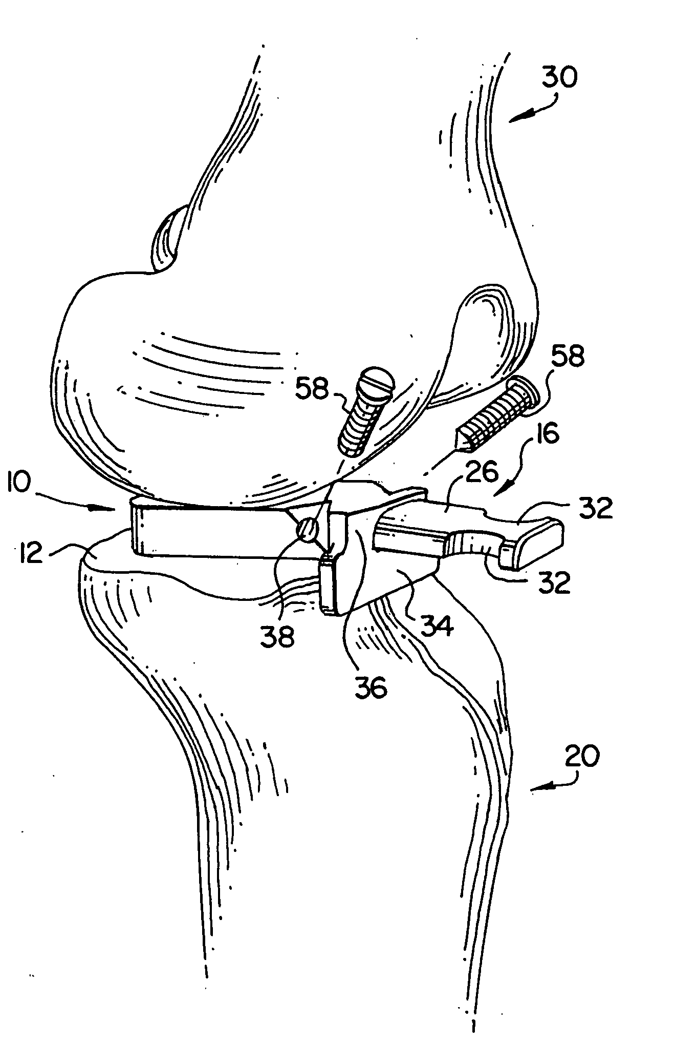
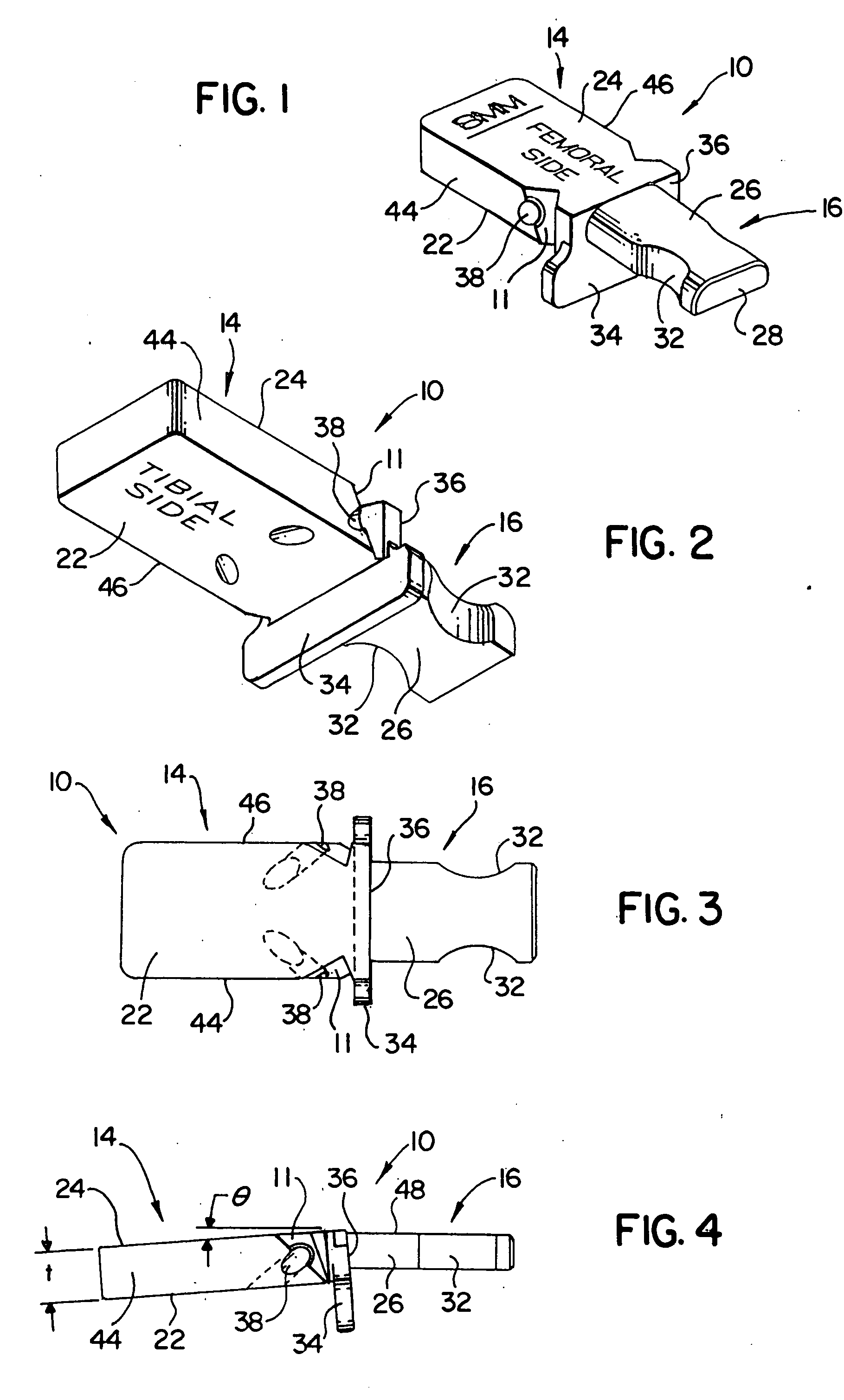
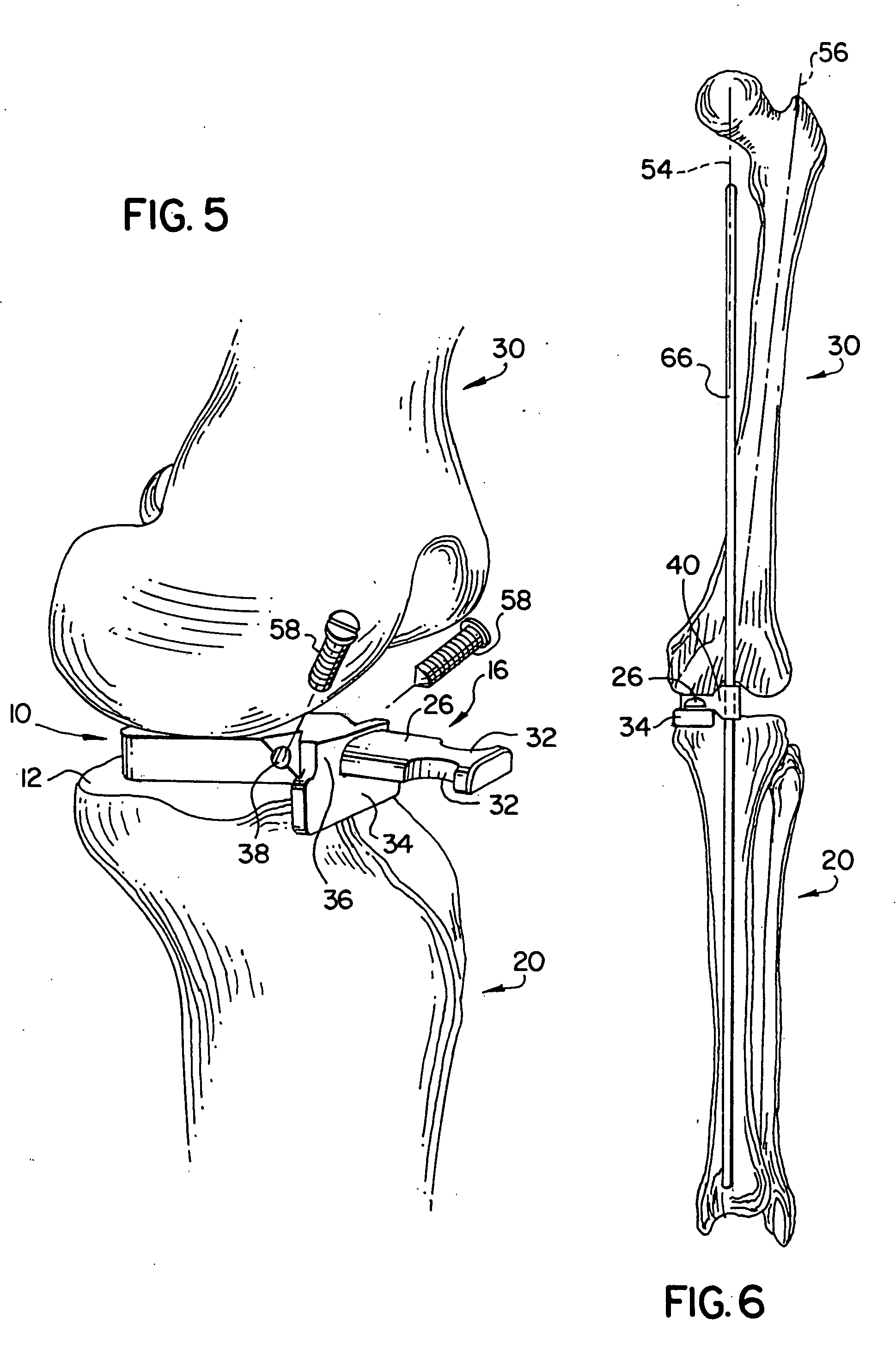
[0027] Turning now to FIGS. 1-5, one embodiment of the present spacer block 10 will be shown and described, with FIG. 5 showing spacer block 10 in position between a tibia 20 and a femur 30. As mentioned above, and as shown in FIG. 5, spacer block 10 is configured to be temporarily positioned upon a resected proximal surface 12 of a tibia 20 during knee arthroplasty. Once in position, a range of motion analysis can be performed, as well as verification of the flexion and extension gaps, all prior to cutting either the distal portion of the femur or the posterior portion of the femur. Further, this embodiment of the spacer block 10 also provides an arrangement for attaching either, or both, an alignment tower (such as tower 40 of FIG. 7) and / or a femoral cutting guide (such as cutting guide 50 of FIG. 10).

[0028] Spacer block 10 preferably includes two main components: a main body portion 14 and an attachment arrangement 16. The main body portion is defined between a distal surface 2...


PUM


Abstract

The present invention relates to one or more tibial spacer blocks used during knee arthroplasty, each configured to be temporarily positioned upon a resected proximal portion of a tibia (essentially mimicking the tibial component of the knee prosthesis), for performing a range of motion analysis and for checking flexion and extension gaps prior to cutting the distal or posterior femur. Preferably, the spacer blocks each include an attachment arrangement configured and arranged to mate with a complementary attachment arrangement of an alignment tower and/or a femoral cutting guide. The alignment tower, which is configured to be used with an alignment rod, is used for verifying the alignment of the limb's mechanical axis when the spacer block is positioned between the tibia and the femur. The femoral cutting guide is used for guiding a cutting member into proper orientation for resecting a distal or posterior portion of a femur.

Description

[0001] The present invention relates generally to one or more components used during knee arthroplasty, where the component(s) are used for: performing a range of motion analysis and verifying the flexion and extension gaps between the femur and tibia; verifying the alignment of the femur relative to the mechanical axis; and / or guiding a cutter during resection of the distal femur and / or the posterior femur. More particularly, the present invention relates to one or more tibial spacer blocks, each configured to be temporarily positioned upon a resected proximal portion of a tibia (essentially mimicking the tibial component of the knee prosthesis), for performing a range of motion analysis and for checking flexion and extension gaps prior to cutting the distal femur and / or the posterior femur. Preferably, the spacer blocks each include an attachment arrangement configured and arranged to mate with a complementary attachment arrangement of an alignment tower and / or a femoral cutting g...

Claims


Application Information

Patent Timeline
IPC IPC(8): A61B17/58
CPCA61B17/1764A61B17/155
Inventor STEFFENSMEIER, SCOTT
Owner SMITH & NEPHEW INC
Why Eureka
Try Eureka