Hammer having vibration absorbing effect

a vibration-absorbing and hammer technology, applied in the field of hammers, can solve the problems of increasing the cost of fabrication, inconvenience to the user during the operation of the hammer, and user easily feeling uncomfortable, so as to achieve the effect of reducing/or obviating the disadvantage of the conventional hammer

Inactive Publication Date: 2006-02-23
CHEN JOHN
View PDF4 Cites 3 Cited by
  • Summary
  • Abstract
  • Description
  • Claims
  • Application Information

AI Technical Summary

Benefits of technology

[0005] The present invention is to mitigate and/or

Problems solved by technology

However, when the striking portion 16 of the hammer hits a workpiece, such as the nail or the like, the vibration applied on the striking portion 16 is directly transmitted through the head 15 and the handle 10 to a user's hand, so that the user easily feels uncomfortable, thereby ca

Method used


Image

  • Hammer having vibration absorbing effect
  • Hammer having vibration absorbing effect
  • Hammer having vibration absorbing effect

Examples


Embodiment Construction

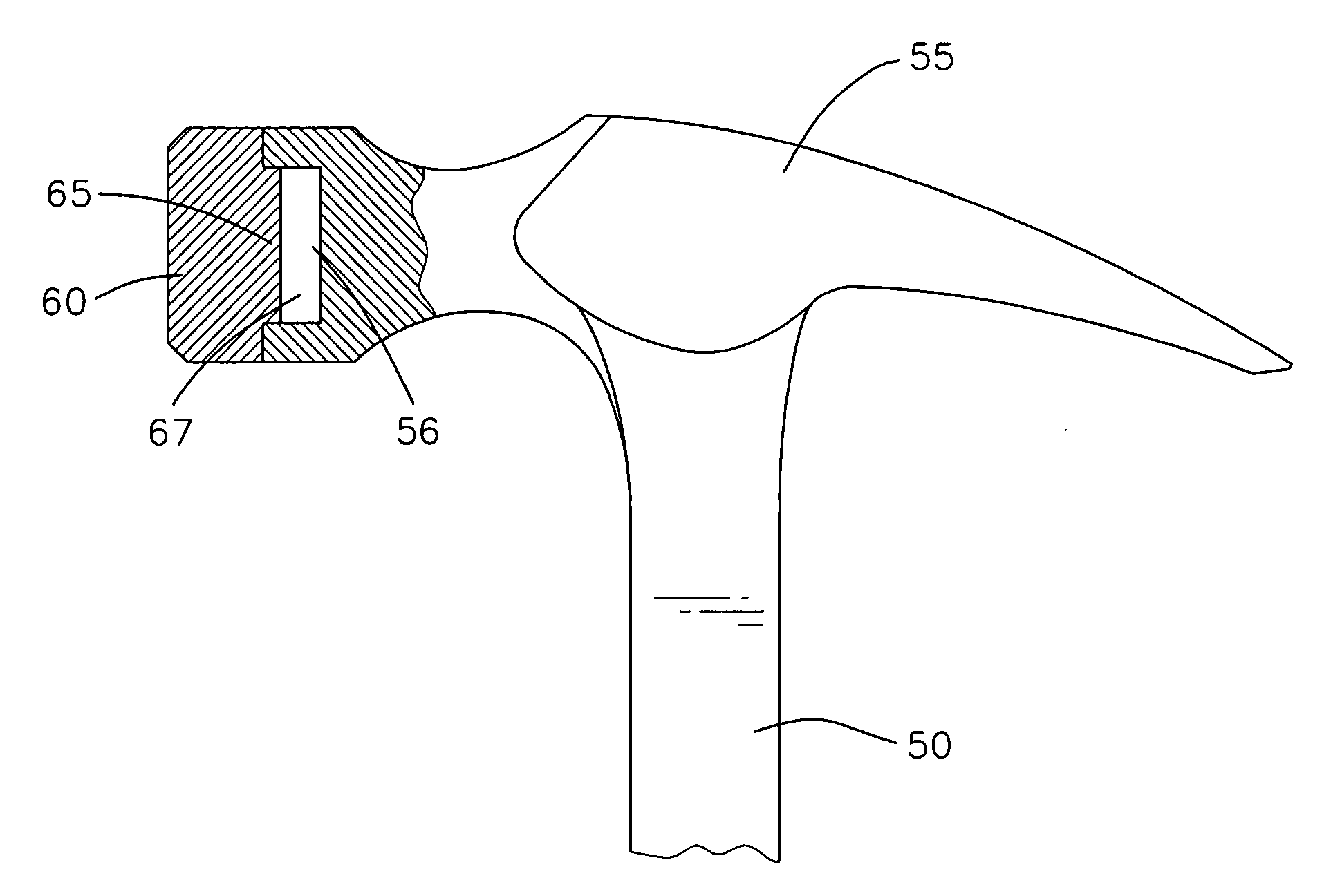
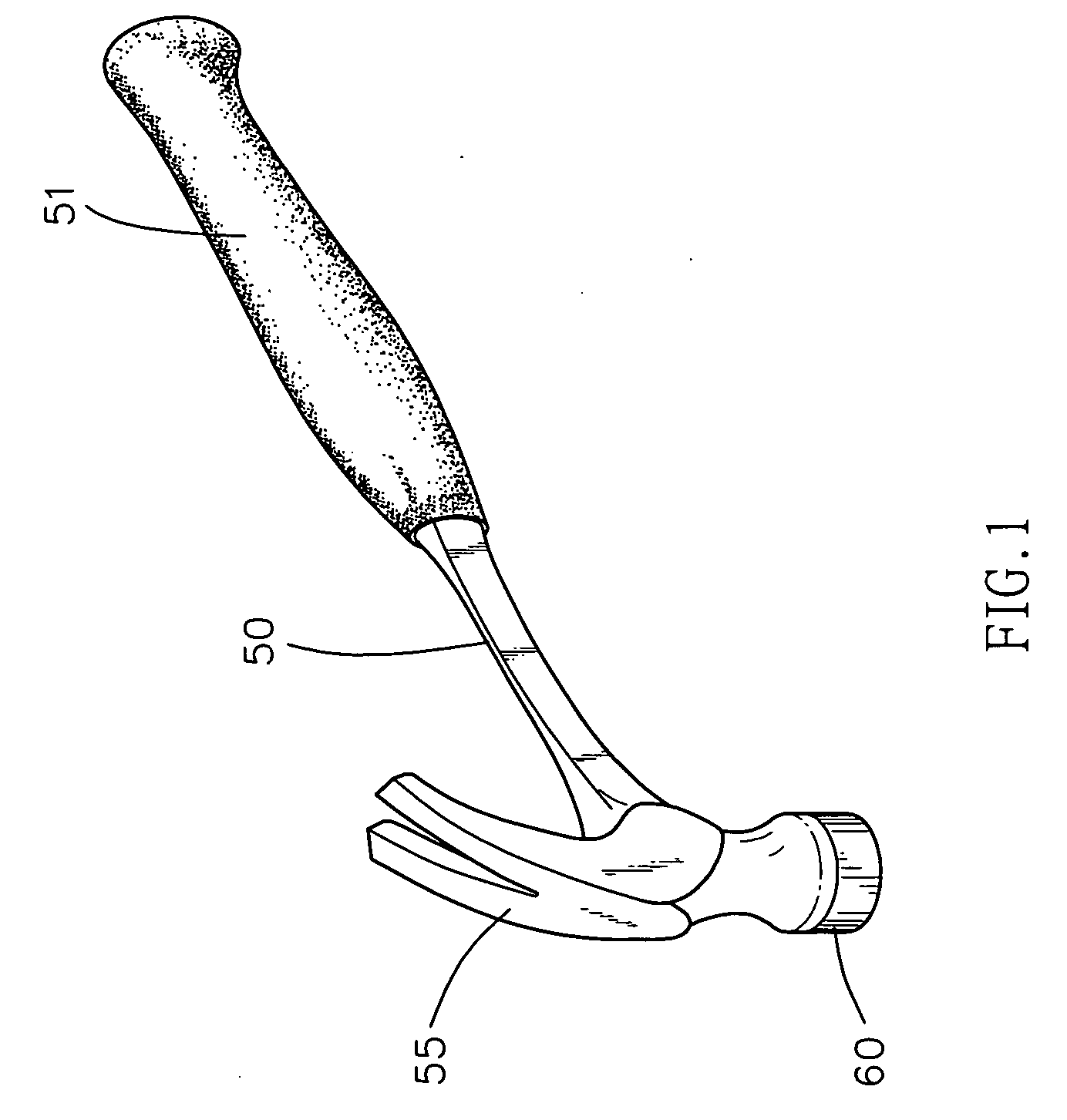
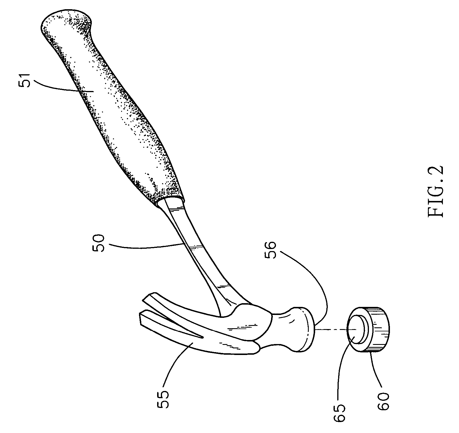
[0020] Referring to the drawings and initially to FIGS. 1 and 2, a hammer in accordance with the preferred embodiment of the present invention comprises a handle 50, a head 55 mounted on a first end of the handle 50, a striking portion 60 mounted on a distal end of the head 55, and a grip 51 mounted on a second end of the handle 50.

[0021] Referring to FIGS. 1-4, the distal end of the head 55 has an end face formed with an insertion recess 56. Preferably, the insertion recess 56 of the head 55 has a circular shape. The striking portion 60 is separated from the head 55 and has an end face formed with an insertion block 65 inserted into the insertion recess 56 of the head 55. Preferably, the insertion block 65 of the striking portion 60 has a circular shape and has a diameter greater than that of the insertion recess 56 of the head 55, so that the insertion block 65 of the striking portion 60 is forced into the insertion recess 56 of the head 55 in a close fit manner. In addition, the...


PUM


Abstract

A hammer includes a handle, a head mounted on the handle and having a distal end having an end face formed with an insertion recess, and a striking portion mounted on the distal end of the head and having an end face formed with an insertion block inserted into the insertion recess of the head. Thus, the cushioning gap between the striking portion and the head provides a vibration absorbing and cushioning effect during operation of the hammer, so that the hammer is operated smoothly and stably, thereby enhancing the striking effect of the hammer, and thereby facilitating a user operating the hammer.

Description

BACKGROUND OF THE INVENTION [0001] 1. Field of the Invention [0002] The present invention relates to a hammer, and more particularly to a hammer having a vibration absorbing and cushioning effect. [0003] 2. Description of the Related Art [0004] A conventional hammer in accordance with the prior art shown in FIG. 5 comprises a handle 10, a head 15 integrally formed on a first end of the handle 10, a striking portion 16 integrally formed on a distal end of the head 15, and a grip 11 mounted on a second end of the handle 10. However, when the striking portion 16 of the hammer hits a workpiece, such as the nail or the like, the vibration applied on the striking portion 16 is directly transmitted through the head 15 and the handle 10 to a user's hand, so that the user easily feels uncomfortable, thereby causing inconvenience to the user during operation of the hammer. In addition, the striking portion 16, the head 15 and the handle 10 are formed integrally to form the hammer, so that the...

Claims


Application Information

Patent Timeline
IPC IPC(8): B25D1/12
CPCB25D1/12
Inventor CHEN, JOHN
Owner CHEN JOHN
Why Eureka
Try Eureka