
Electrical device

Active Publication Date: 2006-02-23
SEG AUTOMOTIVE GERMANY GMBH
View PDF6 Cites 1 Cited by
  • Summary
  • Abstract
  • Description
  • Claims
  • Application Information

AI Technical Summary

Benefits of technology

[0005] The electrical device according to the present invention has the advantage that providing at least two spacers between the at least one electrical conductor and another conductive body can reliably prevent short-circuiting between the conductive body and the conductor. In addition, this type of design permits further miniaturization of the electrical device.
[0006] If the at least one conductor is permitted to protrude from the housing in a circumference surface of an opening and the conductive body is inserted into the opening, then on the one hand, with an intrinsically uninsulated end of the conductor, it is possible to achieve the shortest possible short-circuit-free spacings between the conductor and the conductive body. In addition, this type of design of the at least one conductor makes it possible to shorten the conductor in the opening to a required dimension.
[0007] Before the conductive body is inserted into the opening, the conductors surrounding the opening can, for example, still be connected to one another by a shared middle part that is cut, for example, from the opening by means of a stamping process. The fact that the conductors are initially connected to one another by a middle part also has advantages with regard to the manufacturing process of the housing since the conductors are thus easily held in place despite the high pressures that occur during the injection molding of the housing. This improves the quality of the conductor arrangement.

Problems solved by technology

In addition, this type of design permits further miniaturization of the electrical device.

Method used


Image

  • Electrical device
  • Electrical device
  • Electrical device

Examples


Embodiment Construction

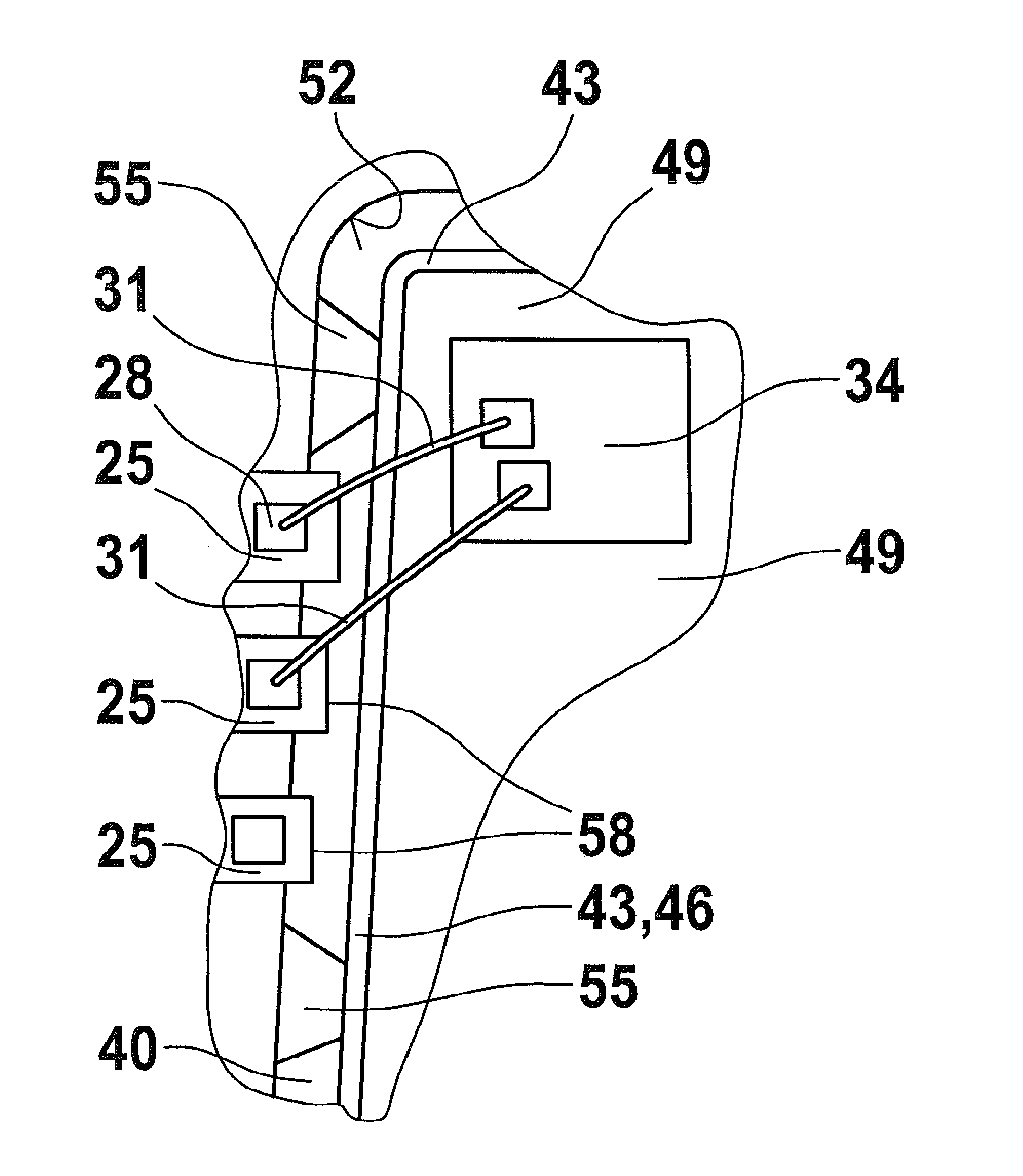
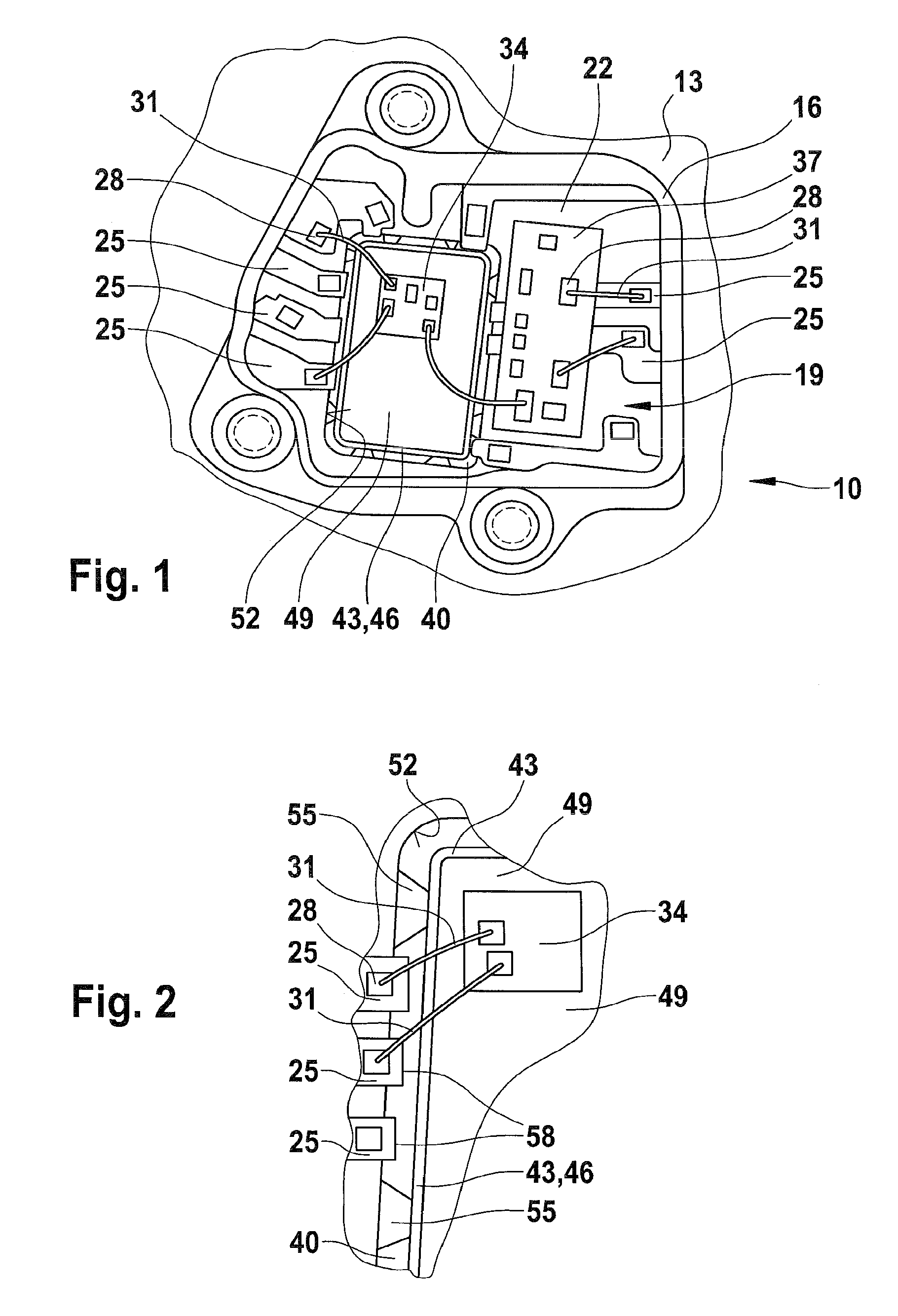
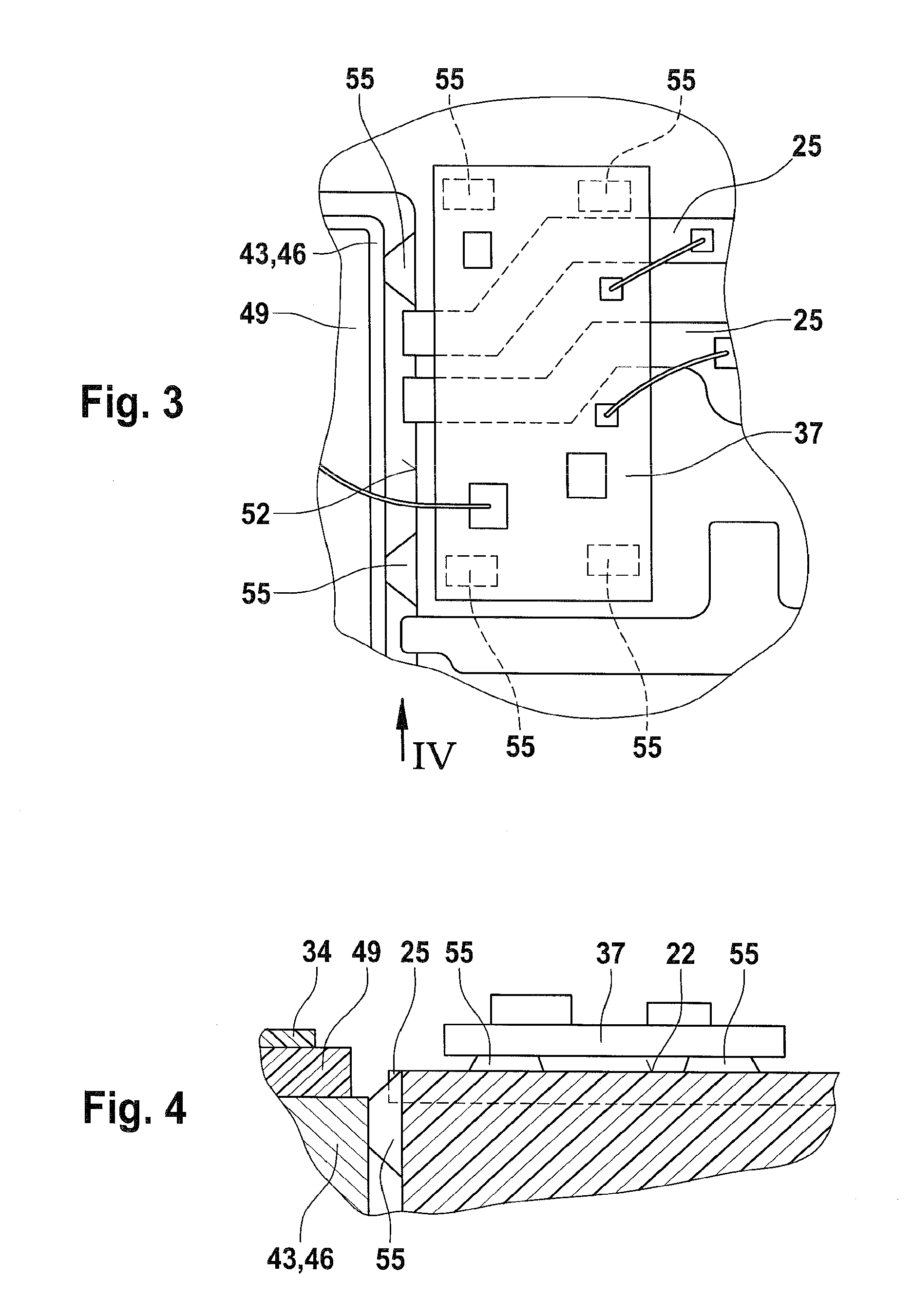
[0013]FIG. 1 is a top view of the electrical device 10. Part of a housing 13 is shown, which has a wall 16 that delimits a housing interior 19. The bottom of the housing interior 19 is delimited by a housing bottom surface 22. The housing bottom surface 22 is constituted in large part by a plastic surface of the plastic housing. But sections of the housing bottom surface 22 are interrupted by one or more electrical conductors 25 accommodated in the housing 13. The conductors 25 are so-called insert parts that are inserted into the injection mold before the housing 13 is actually injection molded and are then at least partially molded into the plastic material of the housing 13. The surfaces of the conductors 25 are provided with so-called bond pads 28 that serve to electrically connect the conductors to a first substrate of 34 by means of so-called bonding wires 31. In this example, these bonding wires 31 also produce an electrical contact with an optional second substrate.

[0014] T...


PUM


Abstract

An electrical device has a housing and a housing surface, at least one electrical conductor accomodated in said housing and interrupting said housing surface in sections so that said housing surface is interrupted, a conductive body which covers said conductor on said interrupted housing surface, and at least two spacers which keep said conductive body apart from said at least one conductor.

Description

BACKGROUND OF THE INVENTION [0001] The present invention relates to an electrical device with a housing and a housing surface, the housing surface being interrupted in sections by at least one electrical conductor accommodated in the housing. [0002] Known electrical devices of this kind are comprised of a housing into which a cooling body made of diecast aluminum is integrated. The integration is achieved by inserting the diecast cooling body into an injection mold and then partially molding the cooling body into the injection molding plastic. This partial molding produces a relatively secure, sealed connection between the cooling body and the hardened plastic housing. The housing contains other insert parts, so-called blanking skeletons, which function as conductor tracks in the housing. These conductor tracks end far enough away from an opening provided in the plastic housing that the entire opening has a closed, rectangular plastic rim. A pedestal of the cooling body protrudes in...

Claims


Application Information

Patent Timeline
IPC IPC(8): H05K5/00
CPCH05K5/0069H01L2224/49171H01L2224/48091H01L2924/00014
Inventor MILLER, HANS-PETERDOEFFINGER, ANDREAS
Owner SEG AUTOMOTIVE GERMANY GMBH
Learn More