Damping Device

a technology of damping device and damping ability, which is applied in the direction of friction dampers, etc., can solve the problems of increased production cost of difficulty in controlling the damping ability of this type, and complicated structure of the damping device of this type, so as to increase the press contact force, control the damping ability thereof, and easy adjustment of damping force or ability

Inactive Publication Date: 2006-10-19
FUKOKU CO LTD
View PDF9 Cites 3 Cited by
  • Summary
  • Abstract
  • Description
  • Claims
  • Application Information

AI Technical Summary

Benefits of technology

[0020] It is in general an object of the present invention to solve the foregoing problems associated with the conventional techniques and more specifically to provide a damping device or damper which has a simple structure, can easily be secured to other devices, has a light weight and can be produced at low cost and further which shows excellent damping characteristics capable of being widely changed depending on the relative differential directions. In particular, it is an object of the present invention to provide a damping device showing damping characteristics, which never requires any space for allowing deformation on the side in which the deformation is large, permits the miniaturization of the device in the axial direction and the reduction of the weight thereof, and can operate in response to even a quite small amplitude, as well as a damping device which can efficiently show the damping of rotational differential motions and which can arbitrarily control the damping characteristics.
[0021] The damping device according to the present invention comprises a housing and a flange member for damping arranged in the housing, wherein at least portions of this flange member apart from the center thereof are composed of an elastic material and inclined with respect to the axial direction or the radial direction of the rotational axis and wherein the flange member is so designed that the peripheral face thereof is brought into contact with the inner wall of the housing at an angle. Thus, there can be provided damping device which 4 has a simple structure, can easily be secured to other devices, has a light weight and can be produced at low cost and further which shows excellent damping characteristics capable of being widely changed depending on the relative differential directions.

Problems solved by technology

The viscous damping device of this type suffers from various problems specified below:
(1) The damping device of this type has a complicated structure and the production cost thereof is thus increased since it is necessary to form flow paths within a housing; and
However, the damping device disclosed in the foregoing gazetted patent likewise suffers from the following problems:
Accordingly, when using this friction-generating mechanism, in particular, as a cylindrical damping device (a shock absorber), the mounting ability thereof is insufficient since the mechanism is hardly rotated in its rotational direction.
However, it is too heavy and it is quite difficult to make the size thereof in its axial direction compact.
In this case, however, the kinetic friction acting between them at a large amplitude is naturally reduced and accordingly, it is quite difficult to establish a well-balanced relationship between the friction generated when amplitudes are quite small and the friction generated when amplitudes are very large.
These oil-type rotary damping devices have been used in a wide variety of fields such as door closers, bearing portions for suspension and / or cover closing-opening mechanisms, but they also suffer from the problems listed below:
(1) The damping device of this type has a complicated structure and the production cost thereof is thus increased since it is necessary to form flow paths within a housing.
Consequently, the devices should be provided with, for instance, liquid-tight and / or sliding or rotational seals and this accordingly requires the establishment of a quite high dimensional precision of the device and this in turn leads to an increased production cost.
(1) This damper is so designed that it is simply provided with contact areas for damping and therefore, the damper can never have damping characteristics having directional properties required when the main case body is in its rotating condition.
Therefore, the damping force of the device would be determined upon the assemblage of the damper and the damper never permits the control of the damping force thereof during the practical use of the same.

Method used


Image

  • Damping Device
  • Damping Device
  • Damping Device

Examples


first embodiment

[0060] An example of the direct acting type damping device or damper according to the present invention will hereunder be described in more detail with reference to the drawings attached hereto.

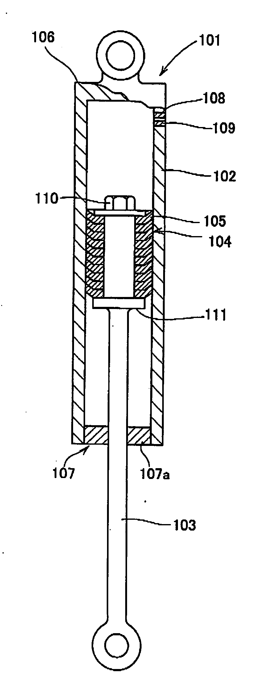
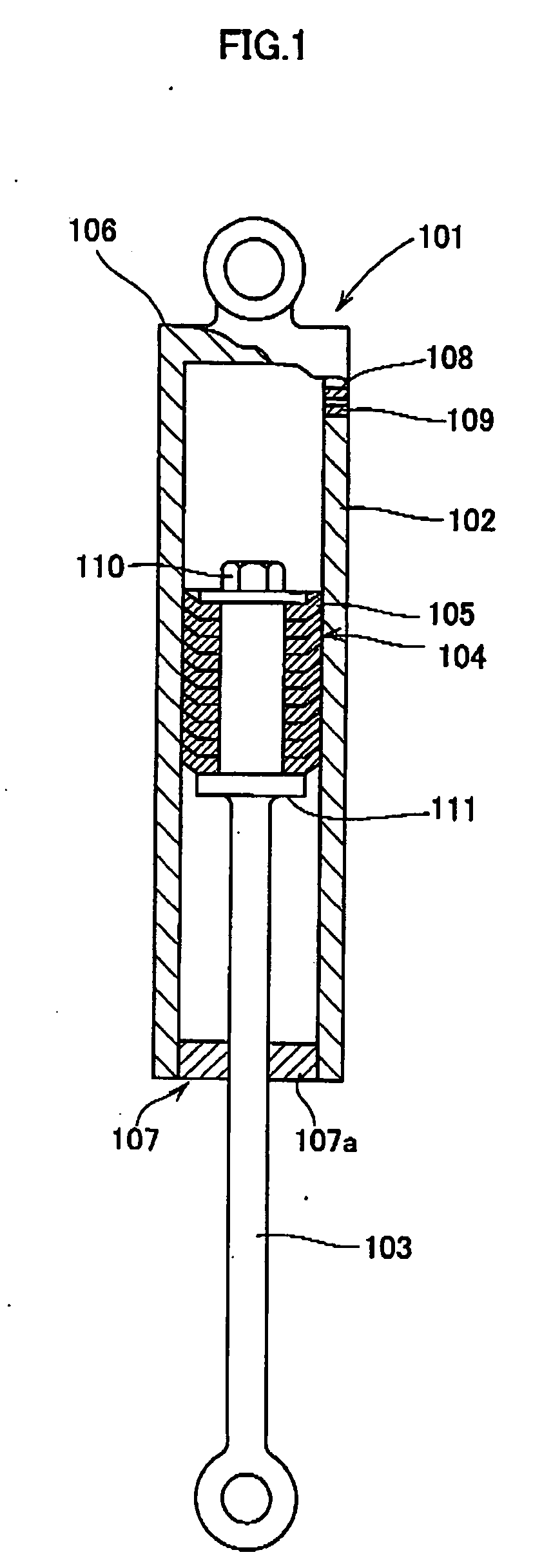
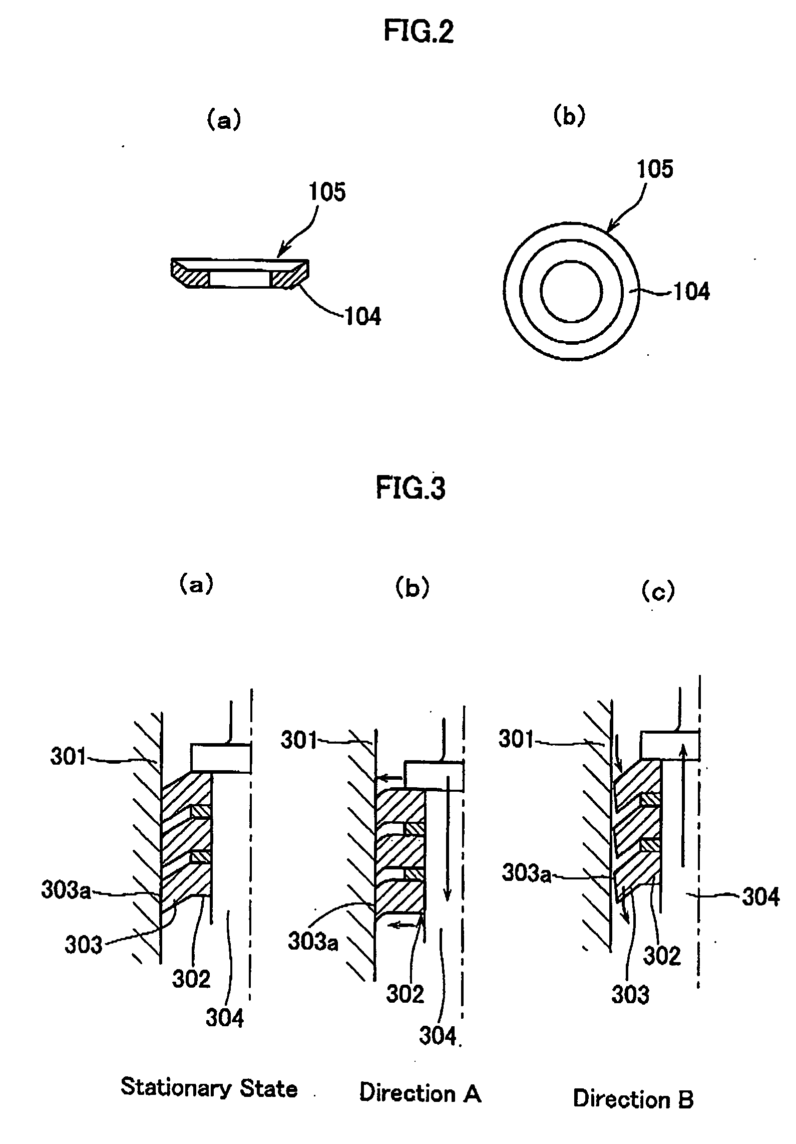
[0061]FIG. 1 is a schematic cross sectional view showing the direct acting type damping device according to the present invention; FIG. 2 shows cross sectional views of the flange member used in this damping device; and FIG. 3 is a constitutional diagram for explaining the operations of the damping device.

[0062] As will be seen from FIG. 1, this damping device is a direct acting type damping device 101 which comprises a cylindrical housing 102, a piston rod 103 undergoing reciprocating motions within the housing and a flange member 104 as a disk-like damping or braking member. This flange member, in its free state, has an outer diameter slightly greater than the inner diameter of the housing to which it is fitted. Further the flange member is unidirectionally tapered, towards the periphery t...

second embodiment

[0086] Then, an example of the rotary acting type damping device according to the present invention will hereunder be described in more detail with reference to the drawings attached hereto.

[0087]FIG. 7 is a schematic perspective view for explaining a disk-like flange member for damping used in the rotary type damping device according to the present invention; FIGS. 8 and 9 are schematic truncated side views (FIGS. 8(a) and 9(a)) and cross sectional views each taken along the line A-A shown in FIG. 8(a) or 9(a) for schematically showing the structure of the rotary type damping device according to the present invention, respectively (FIGS. 8(b) and 9(b)); FIG. 10 is a transverse sectional view showing a variety of shapes of the flange member used in the rotary type damping device according to the present invention; and FIG. 11 is a schematic diagram showing a different variations concerning the convex portions of the flange member used in the rotary type damping device according to t...


PUM


Abstract

A damping device for use in industrial machinery and tools comprising a housing (102, 602) and a flange member (104, 604) arranged in the housing, wherein at least portions of the flange member apart from the center thereof are composed of an elastic material and inclined with respect to the axial direction or the radial direction of the rotational axis and the flange member is so designed that the peripheral face thereof is brought into contact with the inner wall of the housing. This device can generate a damping force which may be drastically changed depending on the operating directions and thus permits stable damping. In the direct acting type one, the flange member (104) is tapered on the corresponding both faces towards the periphery thereof, it never requires the formation of any space for allowing any deformation on the largely deformed side, the device can thus be miniaturized in the axial direction and permits the reduction of the weight thereof and it can operate even in response to motions having a fine amplitude to thus show excellent damping characteristics. In the rotary type one, the flange member (604) comprises an engaging member capable of being engaged with a shaft body (603) and is provided with projected or convex portions (604a) on its outer periphery. The projected portions are inclined towards the radial direction of the rotating shaft to thus efficiently show their excellent differential rotation-damping characteristics and the damping characteristics may arbitrarily be controlled. These damping devices can be used as dampers for suspensions of bicycles, rotary dampers applied to chairs and dampers for opening and closing doors.

Description

TECHNICAL FIELD [0001] The present invention relates to a damping device or a damper and, in particular, to a damping device which is used in, for instance, industrial machinery and tools and which can generate a damping force when there is a differential motion between two members and can generate a substantially different damping force depending on the operating direction thereof. More particularly, the present invention relates to a damping device which can diminish, in particular, a linear reciprocating differential motion and a rotational differential motion. BACKGROUND ART [0002] As damping devices, there has conventionally been known a so-called direct acting type oil damping (viscous damping) device which makes use of the fluid resistance of, for instance, oil such as a shock absorber used in, for instance, automobiles. The viscous damping device of this type suffers from various problems specified below: [0003] (1) The damping device of this type has a complicated structure...

Claims


Application Information

Patent Timeline
Patent Type & Authority Applications(United States)
IPC IPC(8): F16F11/00F16F7/02F16F7/08
CPCF16F7/08F16F7/02
Inventor CHIBA, MASAAKI
Owner FUKOKU CO LTD
Why Eureka
Try Eureka