Methods for driving electrophoretic displays using dielectrophoretic forces

a technology of electrophoretic displays and dielectrophoretic forces, which is applied in the direction of instruments, door/window protective devices, constructions, etc., can solve the problems of inadequate service life of electrophoretic displays, preventing their widespread use, and gas-based electrophoretic media being susceptible to the same types of problems

Inactive Publication Date: 2006-02-23
E INK CORPORATION
View PDF3 Cites 247 Cited by
  • Summary
  • Abstract
  • Description
  • Claims
  • Application Information

AI Technical Summary

Benefits of technology

[0033] applying to the medium an electric field having a second frequency higher than the first frequency, thereby causing the particles to undergo dielectrophoretic motion and producing a second optical state different from the first optical state.
[0050] applying to the medium an electric field having a low amplitude, low frequency component and a high amplitude, high frequency component, thereby causing the particles to undergo dielectrophoretic motion and producing a second optical state different from the first optical state.

Problems solved by technology

Nevertheless, problems with the long-term image quality of these displays have prevented their widespread usage.
For example, particles that make up electrophoretic displays tend to settle, resulting in inadequate service-life for these displays.
Such gas-based electrophoretic media appear to be susceptible to the same types of problems due to particle settling as liquid-based electrophoretic media, when the media are used in an orientation which permits such settling, for example in a sign where the medium is disposed in a vertical plane.
Indeed, particle settling appears to be a more serious problem in gas-based electrophoretic media than in liquid-based ones, since the lower viscosity of gaseous fluids as compared with liquid ones allows more rapid settling of the electrophoretic particles.

Method used


Image

  • Methods for driving electrophoretic displays using dielectrophoretic forces
  • Methods for driving electrophoretic displays using dielectrophoretic forces
  • Methods for driving electrophoretic displays using dielectrophoretic forces

Examples


Embodiment Construction

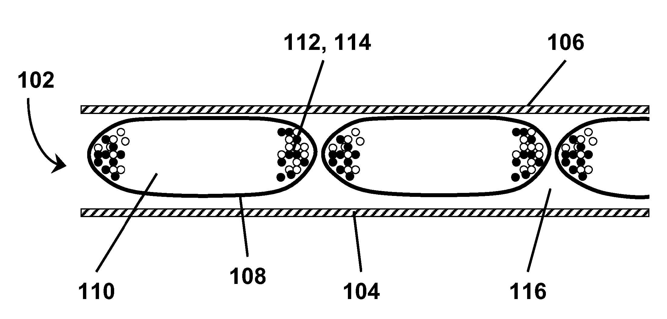
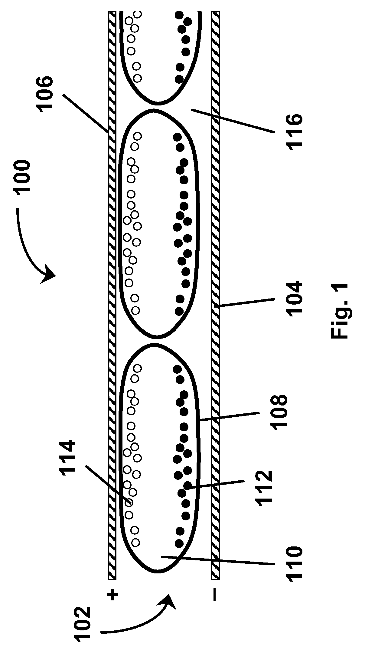
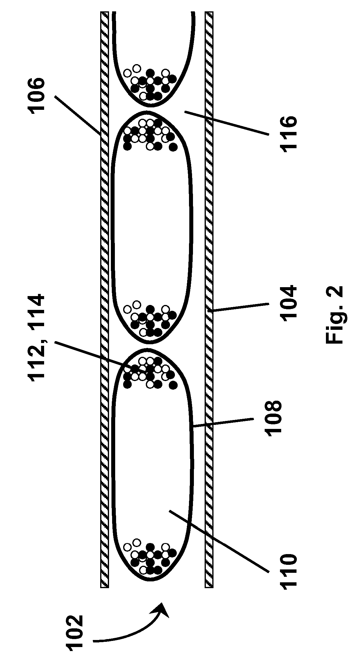
[0063] As indicated above, this invention provides several different methods for operating dielectrophoretic displays. These several methods may be described separately below, but it should be understood that a single display of the present invention may make use of more than one of such methods, either at the same time or as alternative methods of operation at different times. The following description will assume that the reader is familiar with the contents of the aforementioned copending application Ser. Nos. 10 / 907,140; 10 / 687,166 and 10 / 249,973, to which the reader is referred for further details of materials and display construction techniques useful in the displays of the present invention.

[0064] However, before describing in detail the various methods of the present invention, it is believed to be desirable to give some more theoretical consideration to electrophoretic and dielectrophoretic movement of particles within an electrophoretic medium.

[0065] In an electric field...


PUM

PropertyMeasurementUnit
frequencyaaaaaaaaaa
frequencyaaaaaaaaaa
frequenciesaaaaaaaaaa

Abstract

A dielectrophoretic display has a substrate having walls defining a cavity, the cavity having a viewing surface and a side wall inclined to the viewing surface. A fluid is contained within the cavity; and a plurality of particles are present in the fluid. There is applied to the substrate an electric field effective to cause dielectrophoretic movement of the particles so that the particles occupy only a minor proportion of the viewing surface.

Description

REFERENCE TO RELATED APPLICATIONS [0001] This application claims benefit of provisional Application Ser. No. 60 / 605,761, filed Aug. 31, 2004. [0002] This application is also a continuation-in-part of copending application Ser. No. 10 / 907,140, filed Mar. 22, 2005, which itself claims benefit of provisional Application Ser. No. 60 / 555,529, filed Mar. 23, 2004, and of provisional Application Ser. No. 60 / 585,579, filed Jul. 7, 2004. [0003] This application is also a continuation-in-part of copending application Ser. No. 10 / 687,166, filed Oct. 16, 2003 (Publication No. 2004 / 0136048), which itself claims benefit of Provisional Application Ser. No. 60 / 419,019, filed Oct. 16, 2002. Application Ser. No. 10 / 687,166 is also a continuation-in-part of copending application Ser. No. 08 / 983,404, filed Mar. 26, 1999, which is the United States National Phase of International Application No. PCT / US96 / 12000, filed Jul. 19, 1996, which is itself a continuation-in-part of application Ser. No. 08 / 504,89...

Claims


Application Information

Patent Timeline
Patent Type & Authority Applications(United States)
IPC IPC(8): G09G3/34G02F1/167G02F1/1676
CPCG02F1/167G02F2001/1672G02F2001/1676E06B9/24G02F2201/12G09G3/34E06B2009/2464G02F2001/1678G02F1/1676G02F1/1681
Inventor AMUNDSON, KARL R.ARANGO, ALEXI C.JACOBSON, JOSEPH M.WHITESIDES, THOMAS H.MCCREARY, MICHAEL D.PAOLINI, RICHARD J. JR.
Owner E INK CORPORATION
Why Eureka
Try Eureka