
Ultra thin optical joystick and personal portable device having ultra thin optical joystick

a joystick and ultra-thin technology, applied in the field of input modules, can solve the problems of insufficient depth of focus, inability to input numbers or letters at the same time, and the thickness of the indispensable components of the mobile phone is considerable, and achieve the effect of reducing the height of the optical joystick, ensuring the quality of the input, and sufficient depth of focus

Inactive Publication Date: 2006-02-23
CRUCIALTEC +1
View PDF13 Cites 23 Cited by
  • Summary
  • Abstract
  • Description
  • Claims
  • Application Information

AI Technical Summary

Benefits of technology

[0026] The present invention provides an optical joystick and a personal portable device, in which a pointer on a screen is moved according to the movement of a finger moving on the joystick, and further, the height of the optical joystick is more reduced and sufficient depth of focus is provided.
[0027] The present invention provides an optical joystick and a personal portable device which can be manufactured as slim and easy to install and assemble.
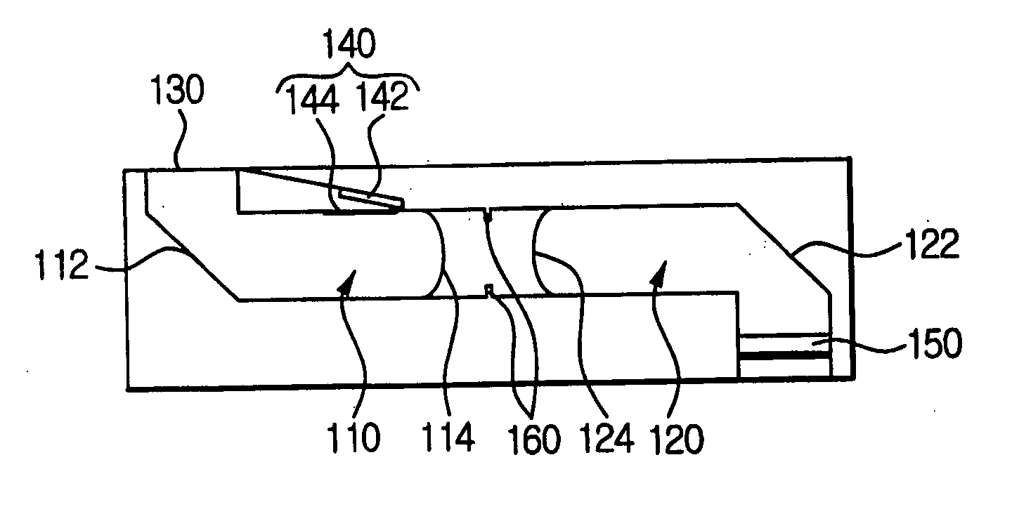
[0030] Accordingly, the light reflected by the object is refracted twice, thereby providing sufficient depth of focus. Since the first and second waveguides include the reflecting surfaces and lens portions, the height of the optical joystick may be reduced to approximately 2 mm. Also, since the reflecting surface and the lens portion are one body, a waveguide may be easily manufactured and the procedure of assembling is simple to mass-produce.
[0032] As the previous embodiment, the first wave guide includes a first reflect surface located below a reading area for sensing the movement of the object and a first plano-convex lens portion condensing the light reflected from the first reflecting surface. The second waveguide facing the first waveguide includes a second plano-convex lens portion and may include an outlet surface without a second reflecting surface. Sufficient depth of focus may be provided by one refraction performed by the first reflecting surface, and the structure of the second waveguide may be simply maintained. Since the first and second waveguides are used, the height of the optical joystick may be reduced to approximately 2 mm. Since the reflecting surface or the lens portion is one body, the waveguide may be easily manufactured and the procedure of assembling is simple to mass-produce.

Problems solved by technology

Since the size and thickness of the indispensable components in a mobile phone are considerable, there is little room for other components in addition to the indispensable components.
Accordingly, inputting numbers or letters may get slower due to the mono movement method.
Generally, a user should memorize the locations and functions of keys for a prompt input, which is troublesome.
Also, the mono movement method can not fully apply the advantages of Graphical User Interface (GUI) environment in the mobile phone.
However, since the purpose of a personal portable device is carrying, an additional pointing device separated from a main body is practically not used as a pointing device of a personal portable device.
However, the structure of a trackball or joystick physically needs spatially considerable room for installation to prevent slimming down of a personal portable device.
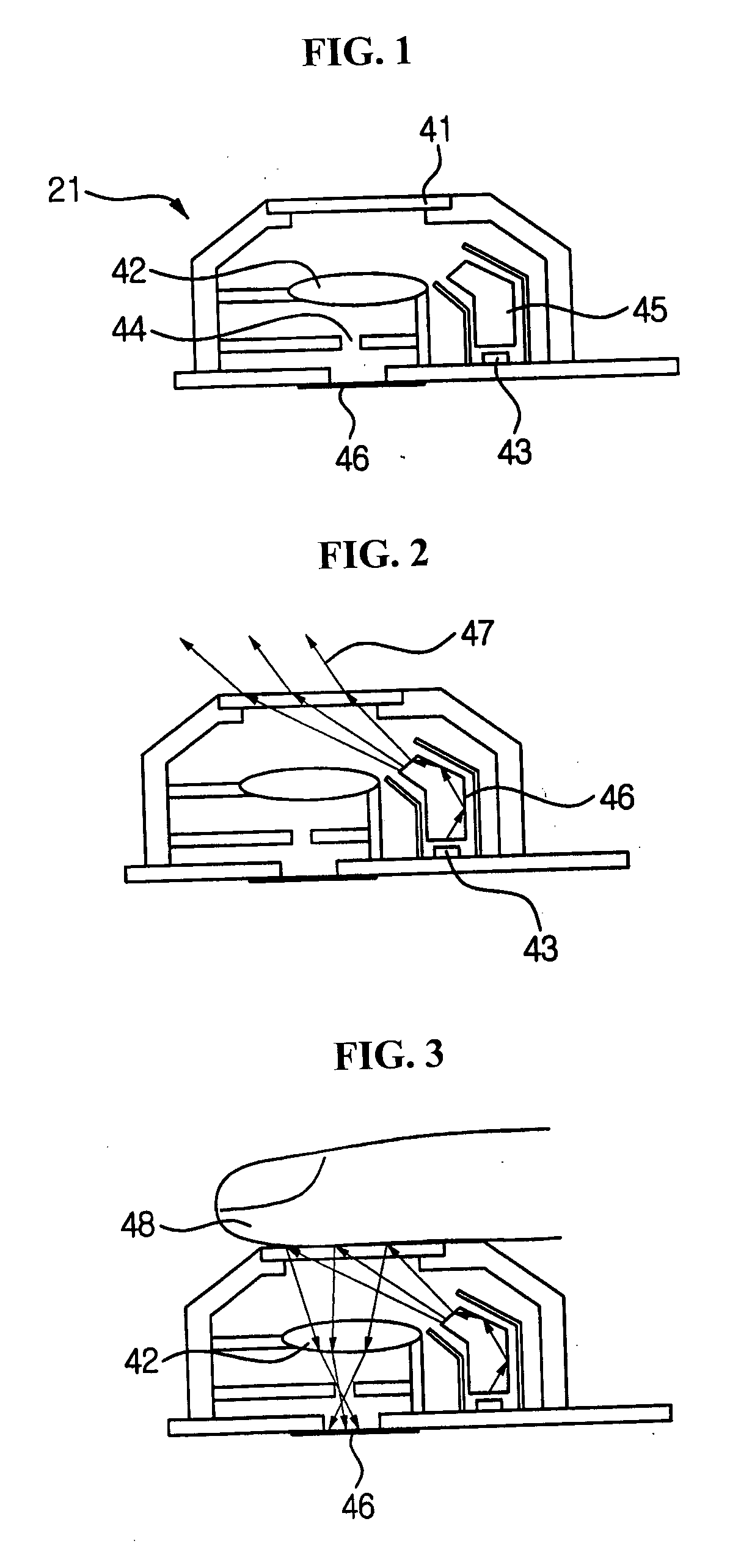
However, the image input device 21 above described can not perfectly slim a personal portable device.
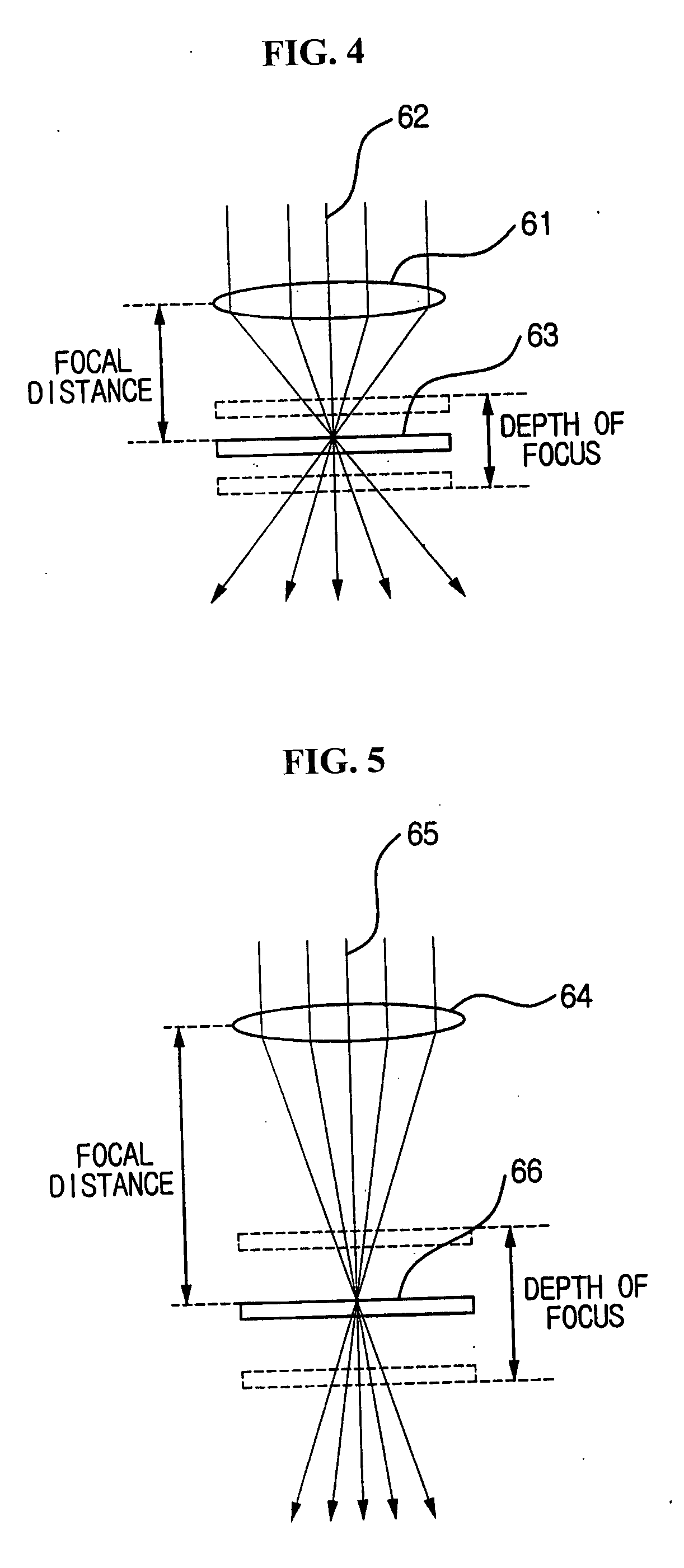
Since there are not only a difficulty to manufacture a ultra precision structure but also the depth of focus, the height of the image input device 21 in the structure of a conventional optical mouse can not be reduced to be less than 2 mm.
Accordingly, in the structure of a conventional optical mouse, the height of basic devices is limited because a cover glass, a lens, and an image sensor are arrayed in a direction of an optical axis and the depth of focus of an optical system is limited.

Method used


Image

  • Ultra thin optical joystick and personal portable device having ultra thin optical joystick
  • Ultra thin optical joystick and personal portable device having ultra thin optical joystick
  • Ultra thin optical joystick and personal portable device having ultra thin optical joystick

Examples


Embodiment Construction

[0048] Hereinafter, exemplary embodiments of the present invention will be more fully described with reference to the accompanying drawings. This invention may, however, be embodied in many different forms and should not be construed as limited to the embodiments set forth herein; rather, these embodiments are provided so that this disclosure will be thorough and complete, and will fully convey the scope of the invention to those skilled in the art. Like reference numerals refer to similar or identical elements throughout.

[0049]FIGS. 6 through 8 are cross-sectional views of an optical joystick according to an embodiment of the present invention.

[0050] Referring to FIG. 6, an optical joystick 100 includes a first waveguide 110, a second waveguide 120, an image sensor 150, a cover glass 130, and a light source portion 140.

[0051] The light source portion 140 includes an LED 142 and a reflecting mirror 144. Since the pixel size of the image sensor 150 included in the joystick 100 is ...


PUM


Abstract

An optical joystick includes a first waveguide including a first reflecting surface located below a reading area for sensing the movement of an object and a first plano-convex lens portion condensing light reflected from the first reflecting surface, a second waveguide including a second plano-convex lens portion facing the first plano-convex lens portion and a second reflecting surface for reflecting light refracted at the second plano-convex lens portion, and an image sensor located below the second reflecting surface. The first reflecting surface and the first plano-convex lens portion form a single body, and the second plano-convex lens portion and the second reflecting surface also form a single body. The reflecting surface and the lens portion are in a single body, thereby notably reducing the thickness of the optical joystick. The first and second waveguides are facing each other, thereby improving refraction and condensing light.

Description

CROSS REFERENCE TO RELATED APPLICATION [0001] This application claims priority under 35 USC § 119 to Korean Patent application No. 20-2004-23760 filed on Aug. 20, 2004, Korean Patent Application No. 10-2004-78941 filed on Oct. 5, 2004, and Korean Patent Application No. 10-2004-113266 filed on Dec. 27, 2004, the contents of which are incorporated herein by reference in their entireties. BACKGROUND OF THE INVENTION [0002] 1. Field of the Invention [0003] The present invention relates to an input module, and more particularly, to an ultra slim optical joystick, whose size is ultra slim, easily installed in a personal portable device such as a mobile phone and a personal portable device including the ultra slim optical joystick. [0004] 2. Description of the Related Art [0005] In conventional personal portable devices such as mobile phones, an input module using a keypad is generally used. A conventional personal portable device includes a plurality of buttons for inputting numbers and l...

Claims


Application Information

Patent Timeline
Patent Type & Authority Applications(United States)
IPC IPC(8): G09G5/00
CPCG06F3/0317G06F2203/0338G06F3/03547
Inventor AHN, KEON JOONPARK, CHULKIM, JAE DONGBAE, JAE HUN
Owner CRUCIALTEC
Learn More