
Touch Sensitive Control Panel

a control panel and touch technology, applied in the field of touch control panels, can solve the problems of reducing the chance of accidental activation, and reducing the chance of accidental activation. the effect of reducing the chance of inadvertent activation

Active Publication Date: 2006-02-23
ATMEL CORP
View PDF9 Cites 114 Cited by
  • Summary
  • Abstract
  • Description
  • Claims
  • Application Information

AI Technical Summary

Benefits of technology

[0005] By allowing certain functions of the appliance to be activated only in response to a pre-determined combination of at least two selections from the plurality of proximity sensor areas, the chance of accidentally activating these functions is reduced. This provides for a domestic appliance which benefits from the advantages of a touch-sensitive control panel but does not suffer the drawback of being prone to inadvertent activation. This provides for a safer appliance. The complexity of the predetermined combination may be selected according to the level of protection against inadvertent activation required. In addition, an elegant and uncluttered control panel can be designed whereby a number different functions are associated with a relatively small number of common sensor areas, the functions being activated according to different pre-determined combinations.
[0006] The pre-determined combination may correspond to a user selecting at least two different proximity sensor areas or to a user selecting a single proximity sensor area at different times. To further reduce the chances of inadvertent activation, the pre-determined combination of at least two selections may need to be made within a specified time period. For example, the combination of selections may need to be made within a time period less than 5, 4, 3, 2, 1, 0.5 or 0.1 seconds. Similarly, selections made within the combination may need to separated by a minimum time such that the specified time within which they are made is more than 0.1, 0.2, 0.3, 0.4, 0.5, 1, 2 or 5 seconds, in order to activate the function with which they are associated.
[0007] In some embodiments of the invention, a function of the appliance activated in response to a user making the pre-determined combination of at least two selections may be subsequently cancelled by the user making only one of the selections comprising the pre-determined combination. For example, a user may be required to select both of two separate proximity sensor areas within a one-second time period in order to switch on an appliance from a stand-by mode. If these two sensor areas are closely spaced, the user can switch on the appliance with a simple sliding motion of his finger from one sensor area to the other. To avoid the need for separate sensor areas for switching the appliance off, the sensor areas associated with switching on the appliance can also be used to switch the appliance off. If desired this can require a similar combination of selections as are required to switch the appliance on. However, in general it is less dangerous to have an appliance accidentally switched off. For safety reasons, switch off should also be an easy operation to perform. It may thus be considered preferable to allow the user to switch off the appliance by selecting any one of the two sensor areas used to switch on the appliance without requiring any predetermined combination of selections to be made.
[0008] In many appliances the use of a position sensitive proximity sensor area for which the driver circuitry is operable to output a detection signal dependent on the position of a touch within said position sensitive proximity sensor can assist operation of the appliance. For example a variable operating parameter of the appliance, such as temperature of a hob or speed of a food blender or washing machine drum, can be varied according a position detected by the position sensitive proximity sensor area. This provides a rapid and intuitive way for a user to set a variable parameter. In order to configure the position sensitive proximity sensor area to vary the variable operating parameter of the appliance, a user may be required to make a pre-determined combination of at least two selections from the plurality of proximity sensor areas, one of which being a selection of the position sensitive proximity sensor. This can help to provide against inadvertent adjustment of the variable parameter. In addition by allowing different variable operating parameters of the appliance, e.g. the temperatures of different heating elements in an oven, to be adjusted with the same position sensitive proximity sensor depending on other selected sensor areas, a number of different variable parameters may be adjusted by a control panel having only one position sensitive proximity sensor area. Position sensitive proximity sensor areas are generally relatively complex and extend over a larger area than more basic binary detectors. Accordingly, a simple and uncluttered control panel can be provided.

Problems solved by technology

However, a problem with touch-sensitive screens in that they can be prone to accidental activation.
This means it is unlikely that a child or a pet, for example, could activate the hob control unintentionally.
This can make such hobs, and other appliances having touch-sensitive control panels, potentially significant sources of danger.
Furthermore, when a hob, or other appliance, with a touch-sensitive control panel is in normal use it can be relatively easy to accidentally change the appliance settings, for example the temperature of a hob, merely by brushing past the control panel when reaching across the appliance or when attempting to adjust some other function of the hob.
This is undesirable since it prevents the appliance from functioning as the user intends, and how he believes it to be, operating.

Method used


Image

  • Touch Sensitive Control Panel
  • Touch Sensitive Control Panel
  • Touch Sensitive Control Panel

Examples


Embodiment Construction

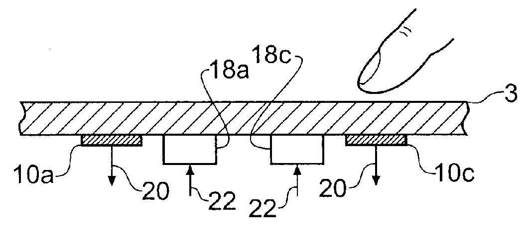
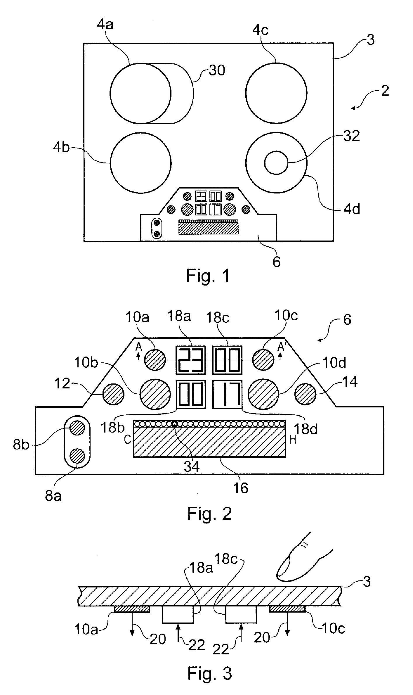
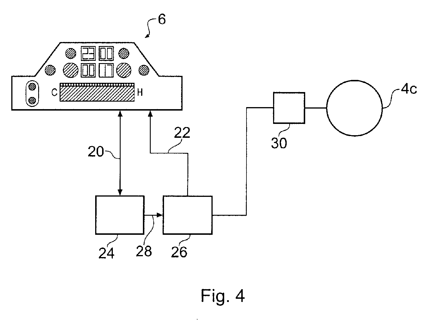
[0033]FIG. 1 schematically shows a plan view of a domestic appliance according to a first embodiment of the invention. The appliance is a hob 2. The hob 2 has an upper surface which comprises a heat resistant glass top 3. The glass top is continuous over the upper face of the hob. This continuous glass top 3 is easy to clean and does not allow fluid or debris to enter the inside of the hob. Below the glass top are mounted four individually adjustable heating elements 4a-d and a control panel 6. The control panel allows a user to control various functions of the hob, for example switching it on and off and adjusting the temperature of the heating elements. The heating elements 4a-d are of the kind conventionally used with glass-topped hobs.

[0034]FIG. 2 schematically shows a plan view of the control panel 6 of the hob 2 shown in FIG. 1 on an expanded scale. The touch-sensitive control panel 6 in this example is a capacitance-based control panel. Although control panels of this type a...


PUM


Abstract

An apparatus for controlling functions of an appliance is described having a touch-sensitive control panel resistant to accidental activation. The touch-sensitive panel has a plurality of proximity sensor areas which may be selected by a user wishing to activate associated functions of the appliance. Driver circuitry coupled to the sensor areas is operable to output detection signals to a controller in response to a user selecting ones of the sensor areas. The controller is configured to activate functions of the appliance in response to these detection signals. For one or more functions of the appliance, for example a switching on function, the controller is configured to only activate the function when a user makes a pre-determined combination of at least two selections from the plurality of sensor areas. This reduces the chances of potentially dangerous functions being activated inadvertently and can further help a designer to provide an intuitive and uncluttered appearance to the control panel.

Description

BACKGROUND INFORMATION [0001] The invention relates to touch-sensitive control panels, also known as touch screens, for controlling appliances. [0002] Touch-sensitive control panels are becoming more common in domestic appliances. In addition to providing more aesthetically pleasing control interfaces, touch-sensitive control panels provide more flexibility than more conventional control panels based on mechanical switches and rotary knobs. Touch-sensitive control panels are also less prone to failure through use due to their lack of moving parts. Touch-sensitive control panels can allow for a sealed interface between a user and the inside of a domestic appliance. This prevents spilt fluid or other debris from entering a domestic appliance through the gaps which surround conventional mechanical switches and knobs. A touch-sensitive control panel additionally provides a surface which can easily be wiped clean. This makes them more hygienic that more conventional control panels as the...

Claims


Application Information

Patent Timeline
Patent Type & Authority Applications(United States)
IPC IPC(8): G09G5/00G06F3/044G06F3/0488G08C19/12H03K17/96H04L17/02
CPCG06F3/044G06F2203/04809G06F3/04886G06F3/04883F24C7/083G06F3/0443
Inventor PHILIPP, HARALD
Owner ATMEL CORP
Learn More