Image processing device

Inactive Publication Date: 2006-02-23
NISSAN MOTOR CO LTD
View PDF6 Cites 49 Cited by
  • Summary
  • Abstract
  • Description
  • Claims
  • Application Information

AI Technical Summary

Benefits of technology

[0013] Therefore, the present invention has been completed with studies mentioned above and has an object to provide an image processing device that is able to execute image conversion with less memory capacity and less load in operation.
[0014] Further, the present invention has an obje

Problems solved by technology

However, upon studies conducted by the present inventors, such a structure is deemed to suffer from errors in production of cameras, errors in mounting the cameras caused by workers for mounting the same and vibrations occurring during vehicle traveling with the resultant occasions for optical axes of camera lenses to result in displacement from predetermined positions, respectively.
However, in such cases, need arises for the address conversion tables to be prepared for directions, in which the optical axes are deviated, and the degrees of deviations, respectively; that is; there is a need for a huge amount

Method used


Image

  • Image processing device
  • Image processing device
  • Image processing device

Examples


first embodiment

[0041] First, an image processing device 1 of a first embodiment according to the present invention is described in detail with reference to FIGS. 1 to 2B.

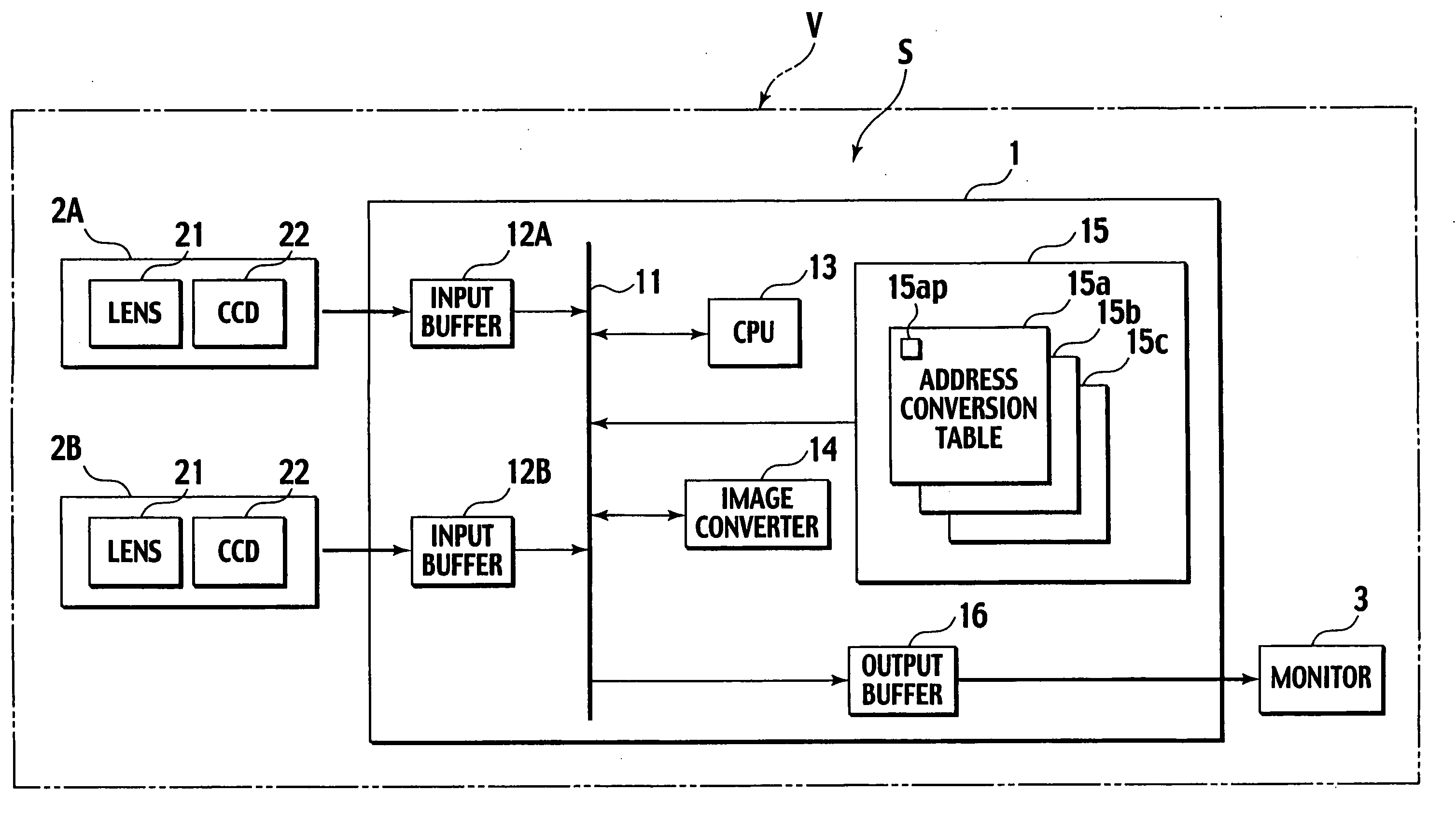
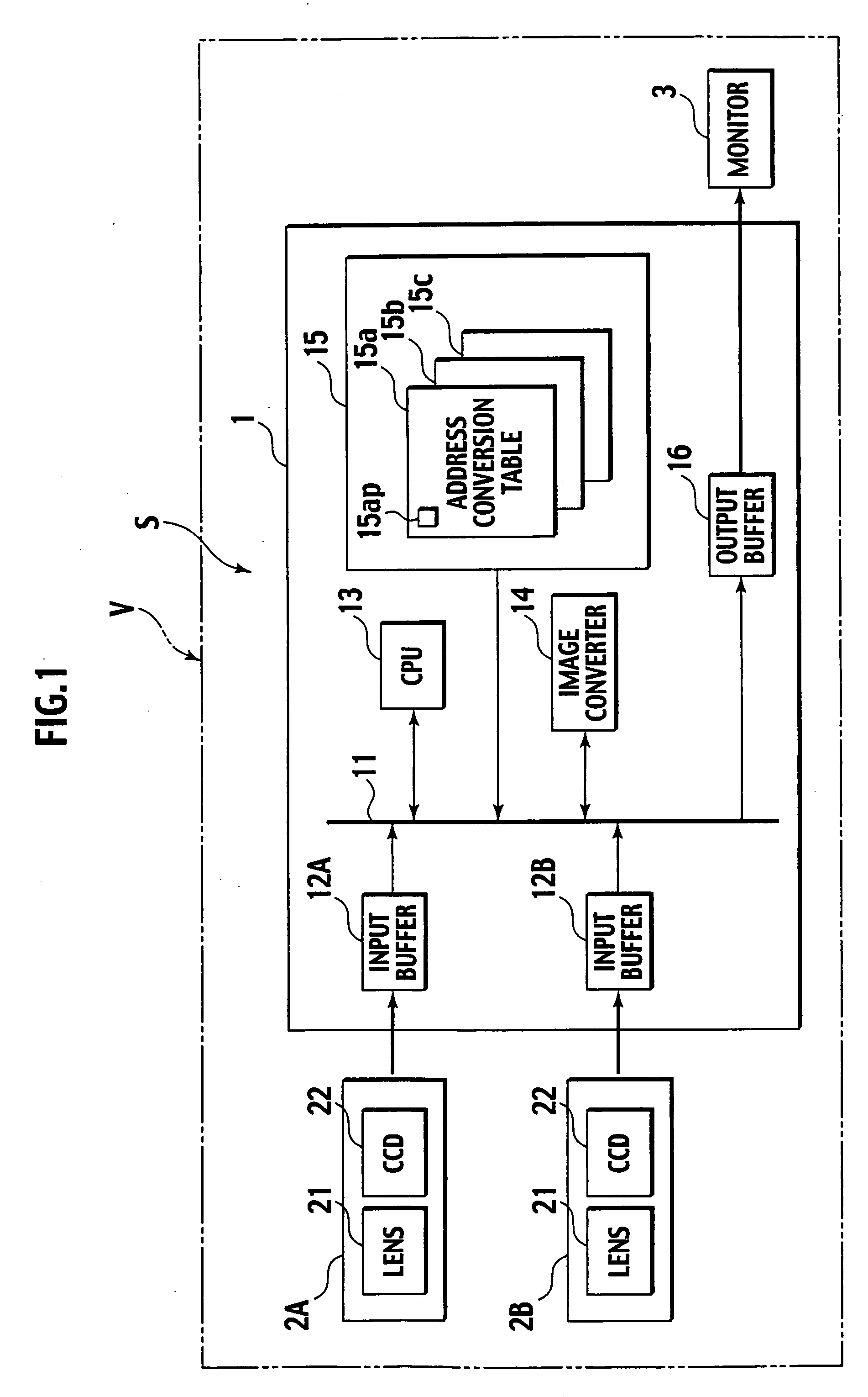
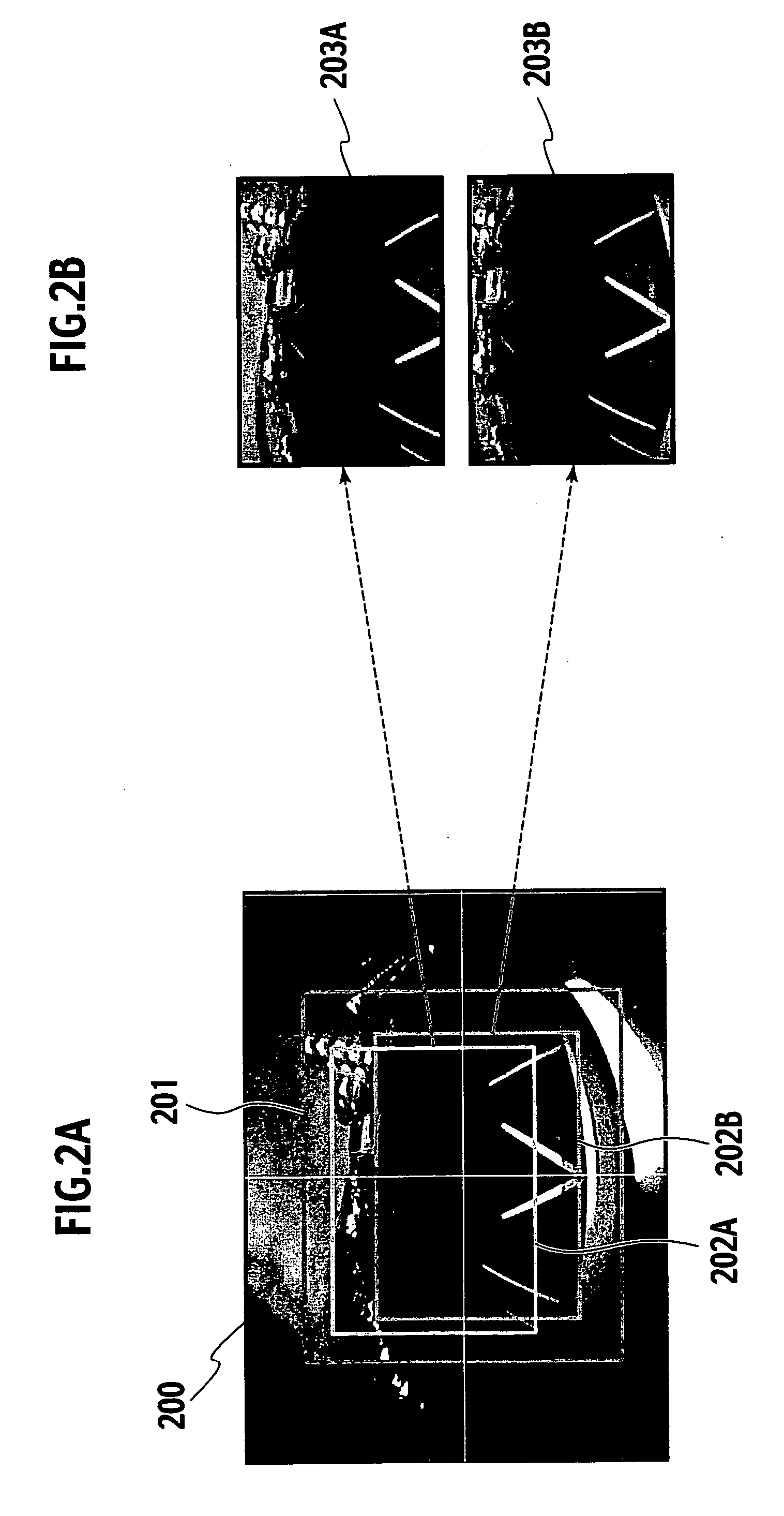
[0042]FIG. 1 is a block diagram showing a structure of a vehicle circumference display system S with the image processing device of the presently filed embodiment; FIG. 2A is a view showing address conversion object images to be used in the image processing device of the presently filed embodiment; and FIG. 2B is a view for illustrating a process by which display images indicative of different positions are displayed based on the address conversion object images shown in FIG. 2A, in the presently filed embodiment.

[0043] [Structure of Vehicle Circumference Display System]

[0044] As shown in FIG. 1, the vehicle circumference display system S, including the image processing device 1, is comprised of a plurality of camera modules 2A, 2B (which when generally named, may also be merely referred to as “camera modules” in brief) and a mo...

second embodiment

[0085] Next, an image processing device of a second embodiment according to the present invention is described below in detail mainly with reference to FIGS. 3A and 3B.

[0086] The image processing device of the presently filed embodiment mainly differs from that of the first embodiment in that a display position is calibrated when information (overlay data) is displayed in a superimposed relation with a camera image picked up by a camera module to assist a vehicle driving. Thus, the same component parts as those of the first embodiment bear like reference numerals to suitably omit description or to provide simplified description with a focus on such a differing point.

[0087]FIG. 3A is a view showing an image area corresponding to a display mode of a monitor in a vehicle circumference display system with the image processing device of the presently filed embodiment and FIG. 3B is a view showing an overlay image 301 shifted with respect to the image area, shown in FIG. 3A, to be super...

third embodiment

[0099] Next, an image processing device of a third embodiment according to the present invention is described below in detail mainly with reference to FIGS. 4A to 4C.

[0100] The image processing device of the presently filed embodiment mainly differs from that of the first embodiment in structure wherein under circumstances where a part of an own vehicle is involved in image pickup areas of the camera modules 2, the image pickup areas of the camera modules 2 are calibrated based on overlay data indicative of an absolute reference position of an asymmetric object such as a vehicle body or a bumper of the own vehicle. Thus, the same component parts as those of the first embodiment bear like reference numerals to suitably omit description or to provide simplified description with a focus on such a differing point.

[0101]FIG. 4A is a view showing an image area corresponding to a display mode of a monitor in a vehicle circumference display system with the image processing device of the p...


PUM


Abstract

An image processing device is provided with an input section through which input image data is inputted from an image pickup device that is obtained by picking up an image of a circumference, a storage section storing an address conversion table describing a relation between address information of the input image data and address information of display image data corresponding to a display resolution, an image processing section processing the input image data to cut out image data, corresponding to the display resolution, from the input image data upon referring to the address conversion table, so as to allow address information of the resultant cut out image data to be converted to address information of the display image data, and an output section outputting the display image data to the display. An address space of the address information of the input image data has a size greater in a height direction or a width direction than that of the display image data.

Description

BACKGROUND OF THE INVENTION [0001] The present invention relates to an image processing device and, more particularly, to an image processing device wherein images around a vehicle circumference are picked up to allow the pickup images to be converted for provision to a driver. [0002] In recent years, attempt has heretofore been made to provide vehicle circumference display devices in driving assist systems that assist drivers for supplementing their visual fields during reverse driving of a vehicle like backing into a garage or parallel parking while pulling over to the kerb, or during running of a vehicle approaching to a blind intersection or a T-shaped road. [0003] Japanese Patent Application Laid-Open Publication No. 2001-163132 discloses a structure wherein cameras pick up images around rearward blind corners of a vehicle and resulting picked-up images are converted to images as viewed from virtual camera positions different from real camera positions. That is, with such an im...

Claims


Application Information

Patent Timeline
IPC IPC(8): H04N5/228H04N5/225
CPCB60R1/00B60R2300/105B60R2300/30B60R2300/302H04N7/181B60R2300/402B60R2300/60B60R2300/8086H04N5/2628B60R2300/305
Inventor SUZUKI, MASAYASUAKATSUKA, TAKESHIYANAI, TATSUMI
Owner NISSAN MOTOR CO LTD
Why Eureka
Try Eureka