Borescope assembly for detecting a condition of a rotating part

a technology for rotating parts and borescopes, which is applied in the field of borescope assemblies, can solve the problems of increasing operating costs, inability to view actively rotating components, and unit inspection,

Inactive Publication Date: 2006-02-23
GENERAL ELECTRIC CO
View PDF35 Cites 45 Cited by
  • Summary
  • Abstract
  • Description
  • Claims
  • Application Information

AI Technical Summary

Problems solved by technology

Existing borescopes, however, are designed for static applications and are unable to view actively rotating components (e.g., turbine blades rotate 3000 RPMs or m

Method used


Image

  • Borescope assembly for detecting a condition of a rotating part
  • Borescope assembly for detecting a condition of a rotating part
  • Borescope assembly for detecting a condition of a rotating part

Examples


Embodiment Construction

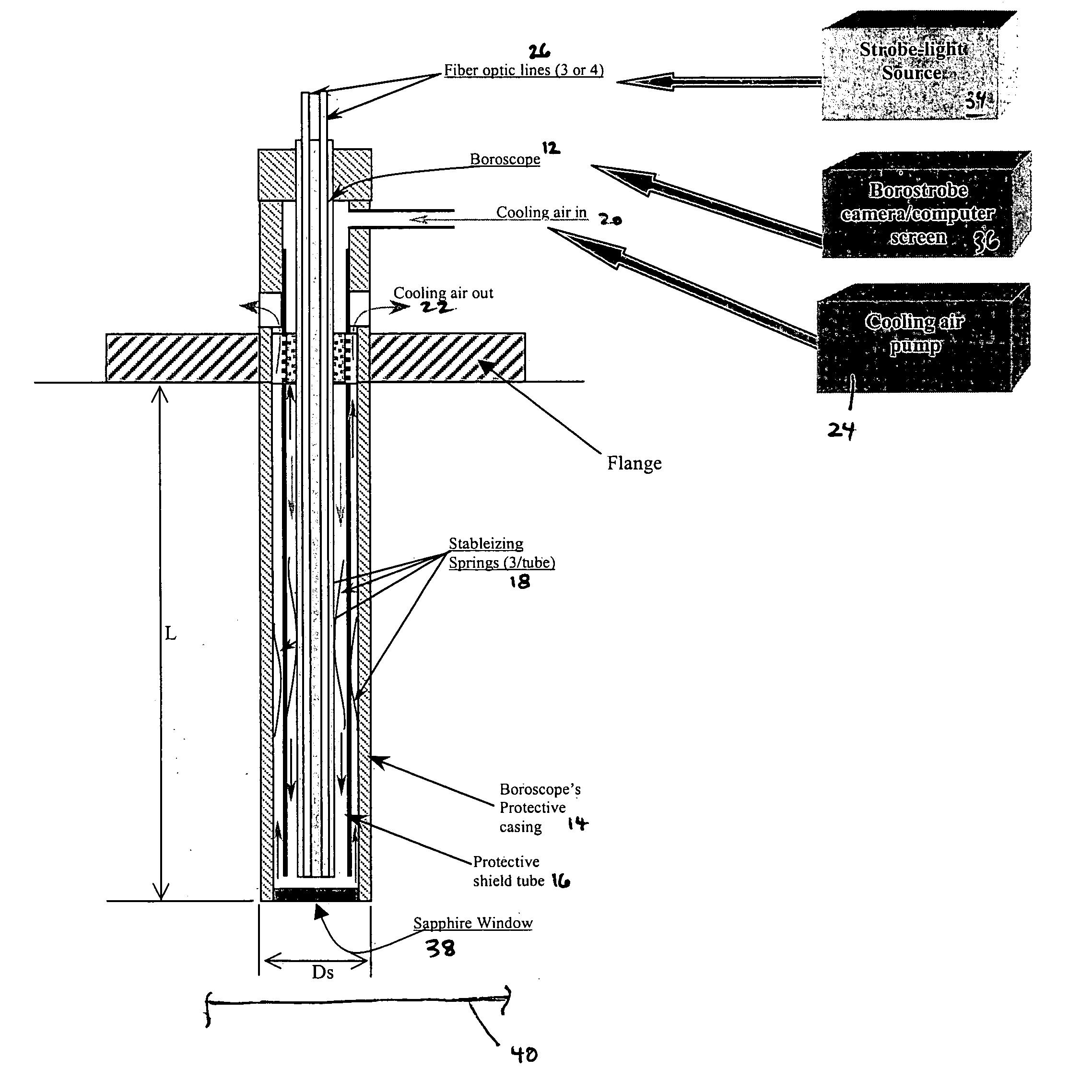
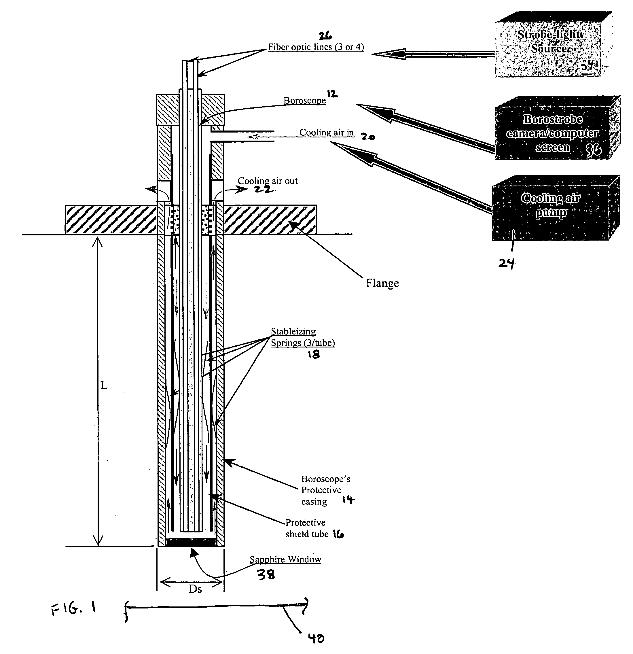
[0007] Borescopes are known for inspection of gas turbine engines. See, for example, U.S. Pat. No. 6,333,812. As described therein, a borescope may include a tube having a distal end and a proximal end received within a housing or chassis. A side viewing in port is provided at the distal end of the tube, and a prismatic reflector is located adjacent the viewing port so as to reflect light from a laterally located object in the general direction of a longitudinal axis defined by the tube. The tube contains axially spaced relay lenses, which together comprise an optical relay operable to relay an image of an object being viewed through the tube to an image viewer within the housing. The image viewer may include an ocular lens mounted in a cylindrical ocular mount along with an eyepiece assembly. A dove prism may be mounted within the tube in order to correct image inversion resulting from reflection by the reflector. As noted, the structure and operation of a borescope are known, and ...


PUM


Abstract

A borescope assembly is suitable for detecting a condition of a rotating part. The assembly includes a borescope disposed in a borescope housing and including structure that relays an image to an image viewer. A plurality of fiber optic lines are disposed in the borescope housing, and a strobe light source is coupled with the fiber optic lines. An image processor is coupled with the image viewer. With this structure, the condition of a rotating part can be detected without stopping the part.

Description

BACKGROUND OF THE INVENTION [0001] The present invention relates to a device for detecting a condition of a rotating part and, more particularly, to a borescope assembly incorporating fiber optic lines coupled with a strobe light source for detecting the rotating part condition. [0002] Borescopes are commonly used for inspection of gas turbine engines to determine if there are any cracks or defects in rotating components such as the turbine blades. Existing borescopes are used to investigate internal parts of the units for cracks or overall integrity of the parts without the need of opening up the unit cover when the unit is cooled and not operating. Typically, the turbine engine includes strategically placed apertures into which a narrow borescope can be inserted. The borescope acts as a camera and delivers an image signal to a display. From the images, a condition of the rotating component, e.g., the existence of cracks, defects, oxidation, can be determined. Existing borescopes, ...

Claims


Application Information

Patent Timeline
IPC IPC(8): G01N21/88
CPCG01N21/954G01N2201/0696G02B23/2476G02B23/2423G02B23/2469G01N2201/0826
Inventor THERMOS, ANTHONY CONSTANTINE
Owner GENERAL ELECTRIC CO
Why Eureka
Try Eureka