Differential interferometers creating desired beam patterns

a differential interferometer and beam pattern technology, applied in the field ofdifferential interferometers, can solve the problems of complex and costly ways to generate desired measurement and reference beam patterns

Inactive Publication Date: 2006-02-23
AGILENT TECH INC
View PDF7 Cites 9 Cited by
  • Summary
  • Abstract
  • Description
  • Claims
  • Application Information

AI Technical Summary

Problems solved by technology

This is a complicated and costly way to generate

Method used


Image

  • Differential interferometers creating desired beam patterns
  • Differential interferometers creating desired beam patterns
  • Differential interferometers creating desired beam patterns

Examples


Embodiment Construction

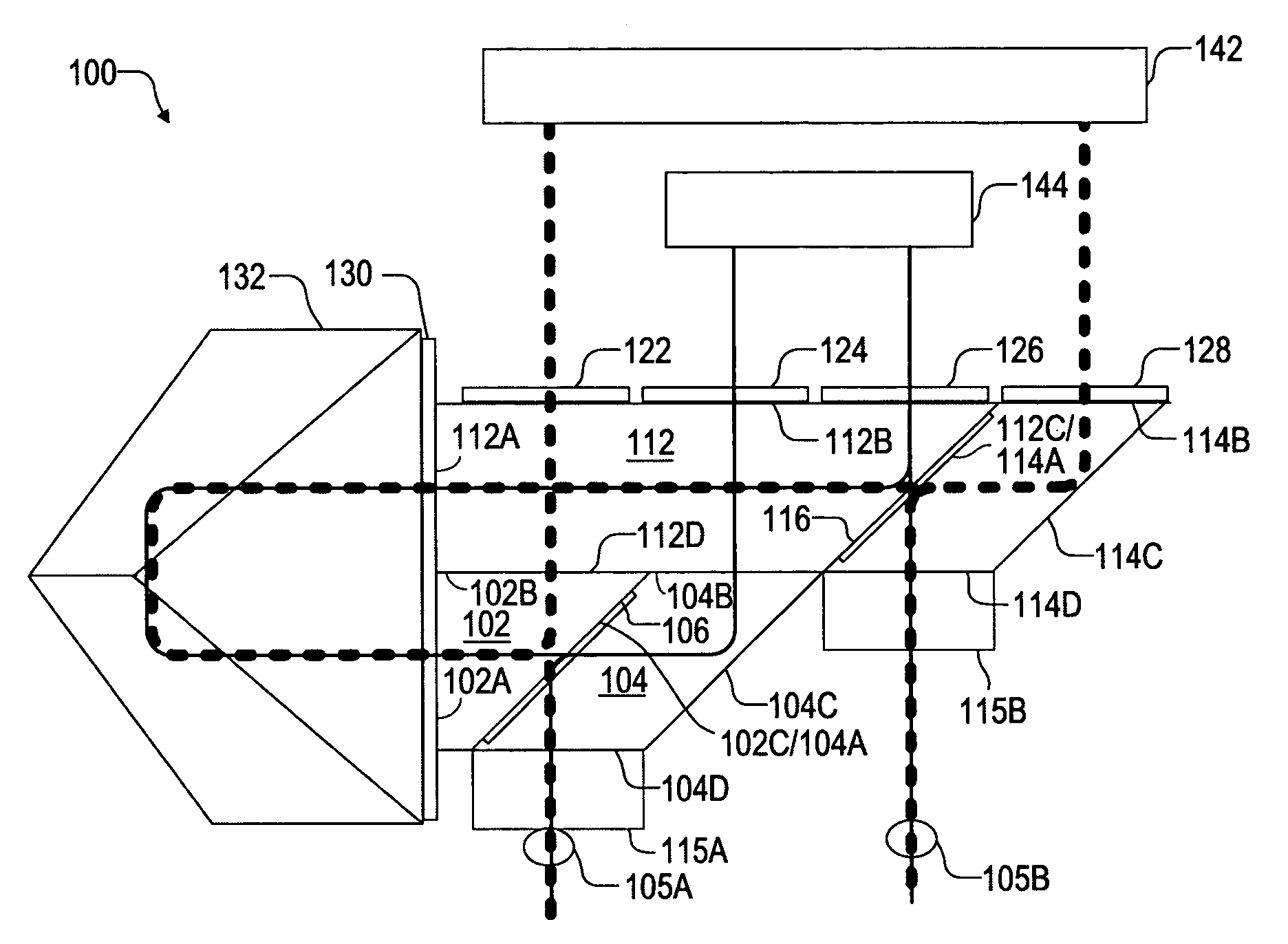
[0005] In accordance with embodiments of the invention, differential interferometer systems incorporate the functions of the shear plate and the polarizing beam-splitter (PBS) with a rhomboid assembly or a shear plate assembly, thereby eliminating the large square PBS and the accompanying large cube corner retroreflectors commonly found in conventional interferometer systems. These systems achieve the desired beam patterns with minimal glass usage. Furthermore, these systems are inherently smaller and can be nested close together and stacked for multi-axis measurements. Accordingly, smaller, lighter, and less costly interferometer systems are provided.

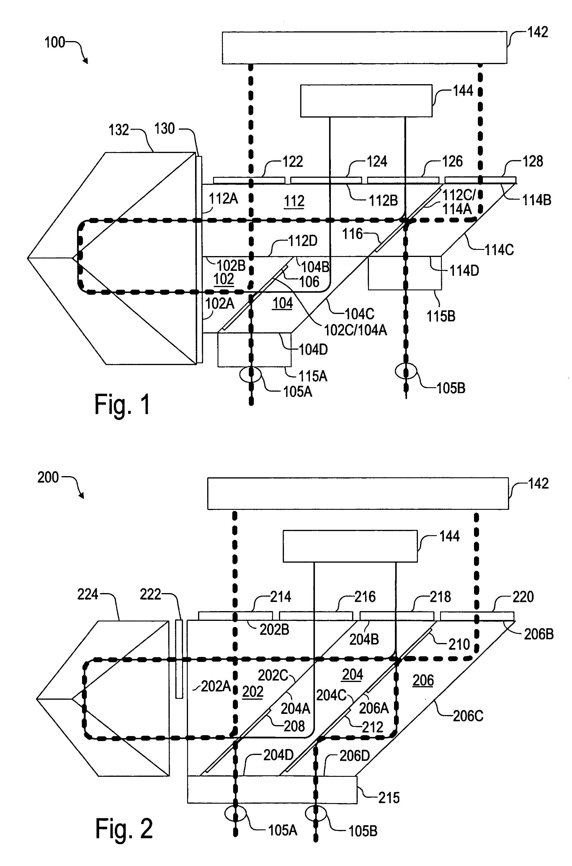
[0006]FIG. 1 illustrates a differential interferometer system 100 in one embodiment of the invention. Interferometer system 100 includes a rhomboid assembly having an upper optical stack mounted atop a lower optical stack. The lower optical stack includes a prism 102 and a prism 104. Prism 102 has a vertical face 102A, a horizontal fa...


PUM


Abstract

An interferometer system includes a rhomboid assembly having a first optical stack and a second optical stack mounted on the first stack. The first stack includes a first prism having an angled face mounted to an angled face of a second prism. The interface between these angled faces includes a first polarizing beam-splitter. The second stack includes a third prism having an angled face mounted to an angled face of the fourth prism. The interface between these angled faces includes a second polarizing beam-splitter. First, second, third, and fourth wave plate elements are located in beam paths between the rhomboid assembly and at least one of a measurement optic and a reference optic. A redirecting optic is located at least adjacent to the vertical faces of the first and the third prisms.

Description

DESCRIPTION OF RELATED ART [0001] In some differential interferometer applications, it is desired to have an inline beam pattern consisting of two reference beam passes between two measurement beam passes (or vice versa), or a 2-dimensional beam pattern consisting of upper left and lower right measurement beam passes and upper right and lower left reference beam passes (or vice versa). U.S. Pat. No. 4,693,605 (“Sommargren”) discloses a way of constructing a differential interferometer system using a shear plate and a separate polarizing beam-splitter (PBS) assembly to achieve the desired 2-dimensional beam pattern. In Sommargren, half-wave plates are inserted between the shear plate and the PBS for proper operation. This is a complicated and costly way to generate a desired measurement and reference beam pattern. Thus, what is needed is a simpler interferometer system that eliminates the separate PBS assembly while achieving the desired beam pattern with minimal glass usage. SUMMARY...

Claims


Application Information

Patent Timeline
IPC IPC(8): G01B9/02
CPCG01J9/0215G01J2009/0261G01B2290/70G01B9/02003G01B9/02018G01B9/02051
Inventor FINE, KEVIN R.FELIX, GREG C.BOCKMAN, JOHN J.WOOLVERTON, DOUGLAS P.
Owner AGILENT TECH INC
Why Eureka
Try Eureka