Structure for hanging an electronic device
- Summary
- Abstract
- Description
- Claims
- Application Information
AI Technical Summary
Benefits of technology
Problems solved by technology
Method used
Image

Examples
Embodiment Construction
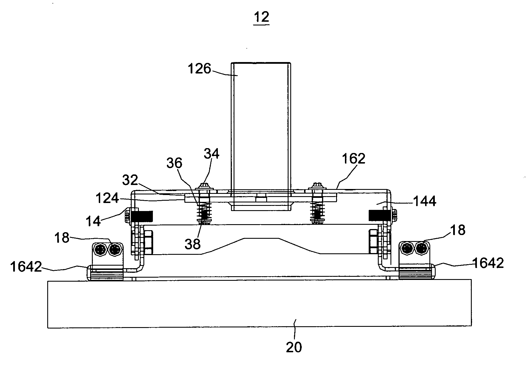
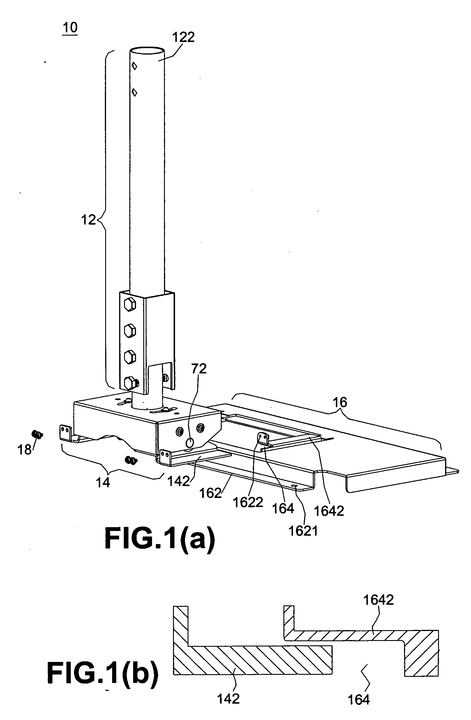
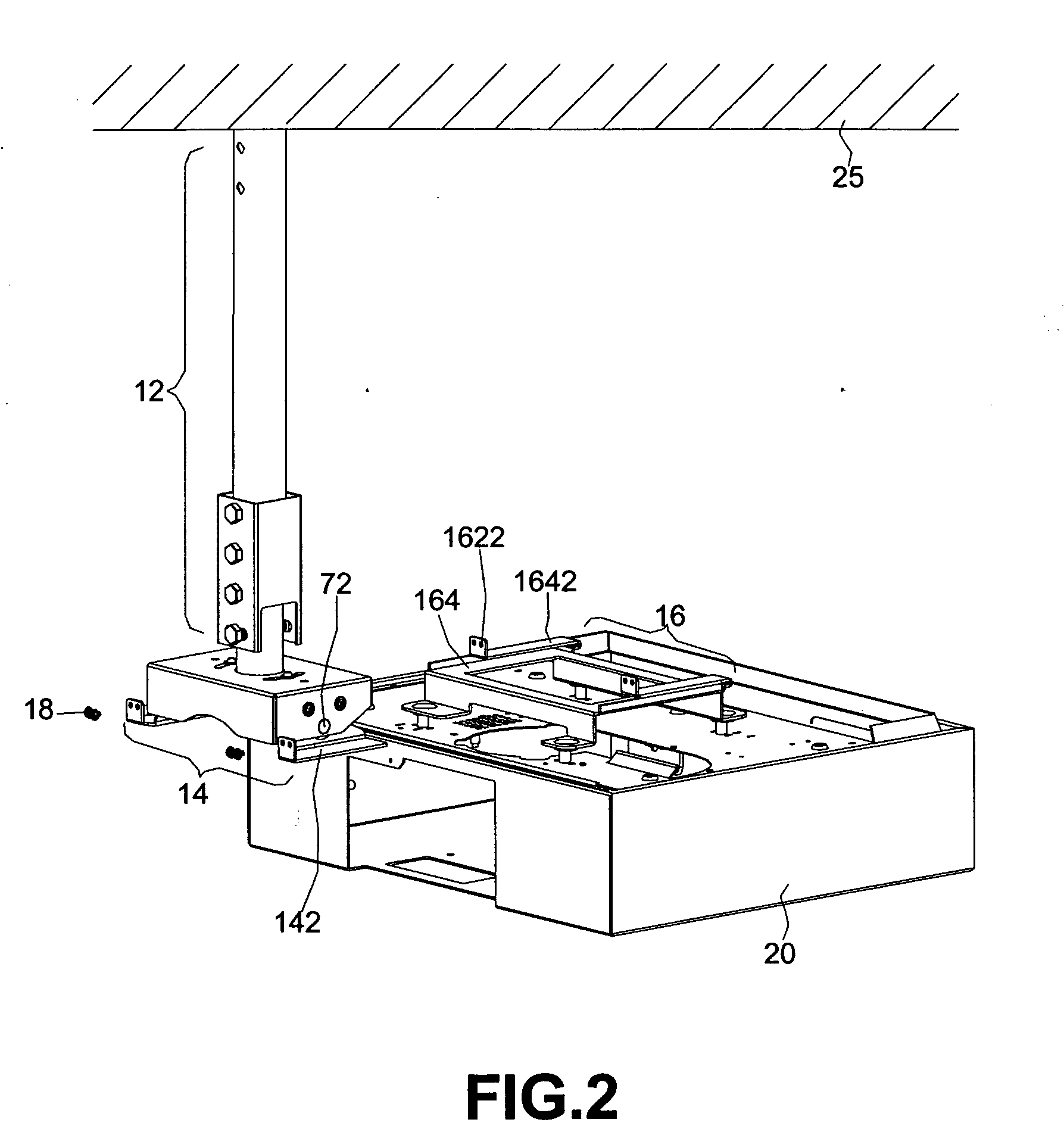
[0022] A structure for hanging an electronic device is disclosed in FIG. 1(a). The structure 10 includes a supporting element 12, an adaptive element 14 and a carrying element 16. The supporting element 12 connects to the adaptive element 14. One edge 122 of the supporting element 12 is fixed to the ceiling 25. The carrying element 16 includes a base 162. The base 162 defines a screw hole 1621, such that a screw can pass through the screw hole 1621 to secure the carrying element 16 on the top of the electronic device (not shown). The base 162 has a rail 164 and the rail 164 has an upper supporting plane 1642. A sliding axle 142 corresponding to the rail 164 is disposed on the bottom of the adaptive element 14. The sliding axle 142 can move within the rail 164, as shown in FIG. 1(b).
[0023]FIG. 1(b) is an enlarged view of the rail 164 and the sliding axle 142. As the sliding axle 142 slides into the rail 164, the sliding axle 142 contacts the upper supporting plane 1642, and the uppe...
PUM
 Abstract
Description
Claims
Application Information
PatSnap Eureka turns technology decisions into work you can execute. Powered by our Innovation Knowledge Graph, it runs expert workflows across engineering, life sciences, materials and intellectual property. Get your review-ready output in minutes.


