Cooperative vehicle control system

a vehicle control system and cooperative technology, applied in vehicle position/course/altitude control, process and machine control, instruments, etc., can solve problems such as interference, interference, and interference, and achieve the effect of determining the potential effectiveness of each subsystem control uni

Inactive Publication Date: 2006-02-23
HONDA MOTOR CO LTD
View PDF12 Cites 42 Cited by
  • Summary
  • Abstract
  • Description
  • Claims
  • Application Information

AI Technical Summary

Benefits of technology

[0006] In further accordance with the present invention, a first function of the subsystems is to be responsible to control its own actuation dynamics particular to its own hardware / electronics in such a way as to have consistent and predictable control application characteristics. A second function is that each subsystem is required to report the status of its operational state back to the main ECU (i.e., to the higher level algorithms responsible for body motion control, traction control, and stability control) as part of the overall diagnostics such that the main ECU can determine the potential effectiveness of each subsystem control unit. A third function is that each subsystem has a communication link to the main ECU wherein it receives priority requests from the main ECU to perform specific control tasks such as brake moment application (in the case of a brake subsystem), drive torque re-distribution (in the case of a controllable driveline system), engine torque reduction or addition (as in the case of an engine subsystem), suspension vertical force augmentation (as in the case of an active suspension), front and / or rear wheel steer augmentation (as in the case of an active steer system), etc. This direct link between the main ECU to each subsystem permits conflict resolution and prioritization in the event of conflicts between the sub-algorithms calculating changes to the subsystems. Each subsystem is to maintain it's basic functionality as well as act upon prioritized requests from the main ECU.

Problems solved by technology

However, many of these systems may have differing strategies to control various vehicle response parameters and conditions and lend themselves to interference.
In some cases actions of two control systems attempting to perform similar function or working in a similar domain of operation (such as controlling wheel slip, vehicle yaw rate, etc.) can have interference.
Depending on how the systems are calibrated it is possible to have interference wherein the driveline system attempts to increase wheel torque on a given wheel, while the brake system attempts to reduce the wheel torque.
This situation occurs because each control system has different targets for wheel slip and / or yaw control using reference signals for the control that may not be calculated in the same manner, hence interference occurs.

Method used


Image

  • Cooperative vehicle control system
  • Cooperative vehicle control system
  • Cooperative vehicle control system

Examples


Embodiment Construction

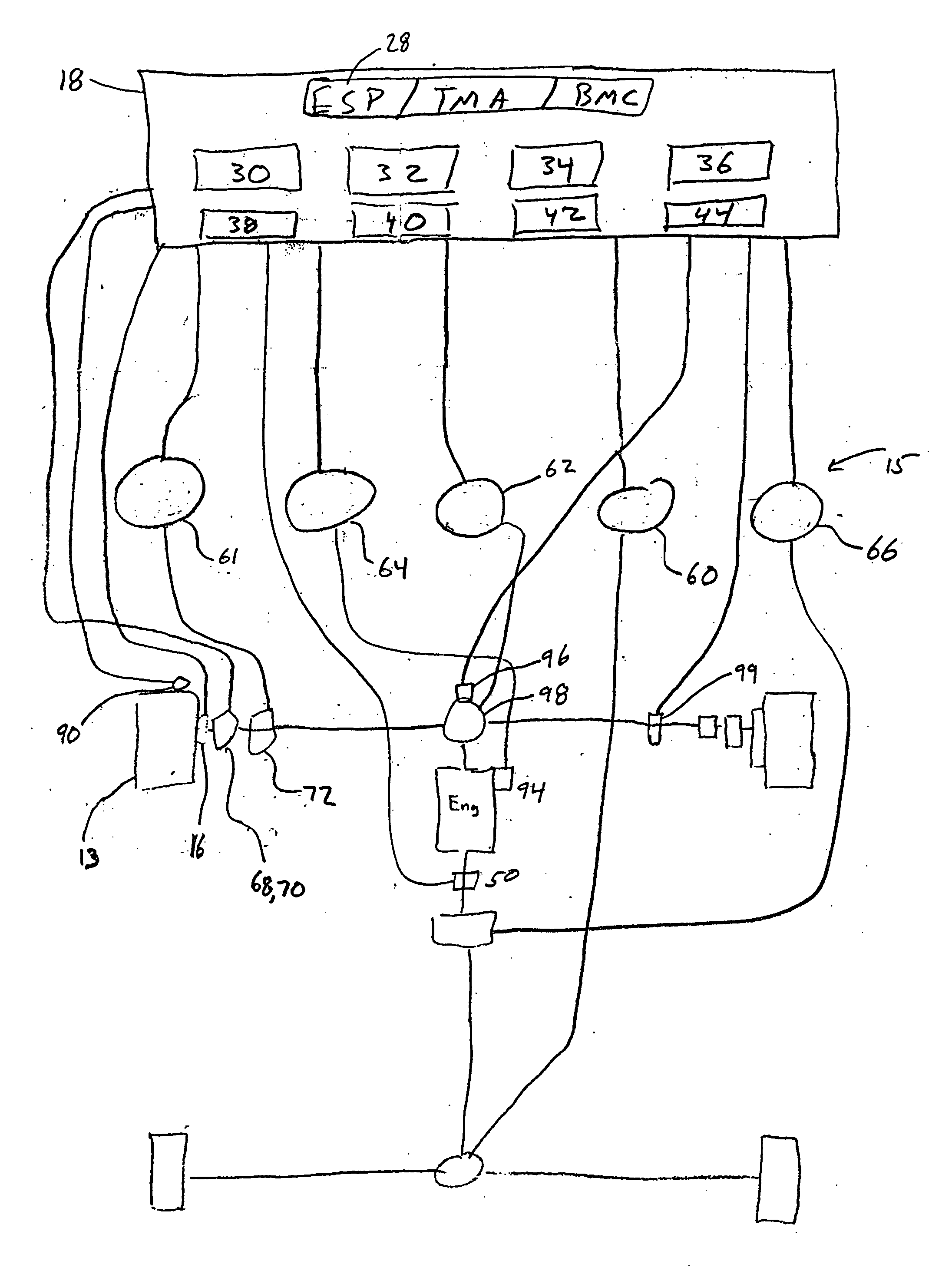
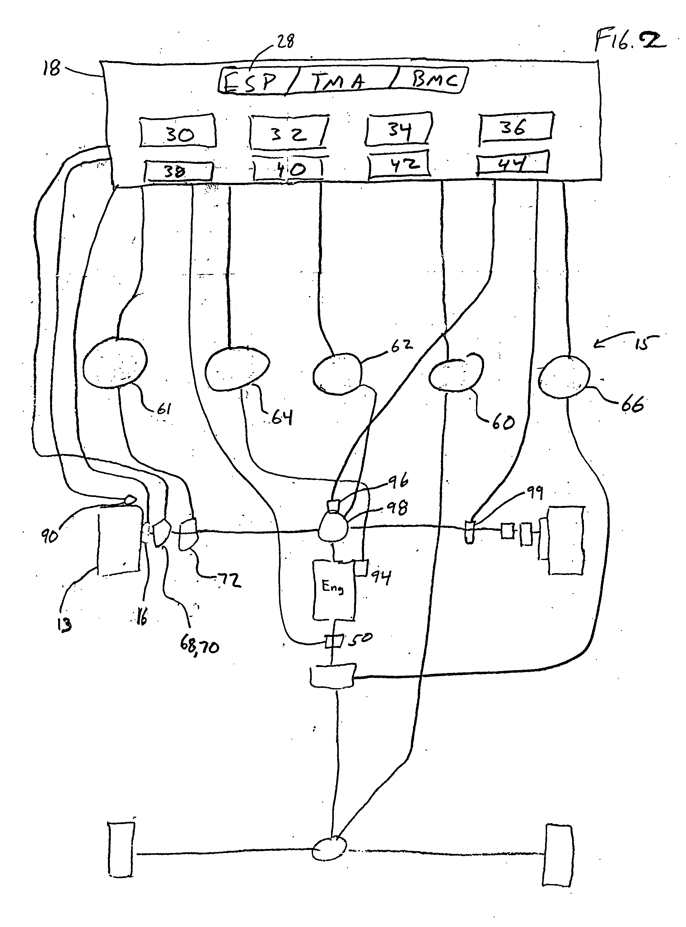
[0011] Referring to FIG. 3, an overall vehicle control system 10 is provided that uses the vehicle driver's initial commands and through various subsystems and feedback from subsystem output and sensor data provides superior vehicle control. Sensors 12 provide information regarding the vehicle's operative state. The vehicle control system 10 includes a set of driver generated control inputs 16, a high level controller (HLC) 18, and one or more sub-algorithms. The sub-algorithms are operable, in response to sensed conditions and user input, to actuate slave control units 15. The slave control units 15, which receive signals from a series of sensors 12 and interact with series of actuators 14, respond to the actuation of the control algorithms. The high level controller (main ECU) 18 may incorporate one or more algorithms utilizing feed-forward control to calculate control inputs for various subsystems. Some algorithms are designed to anticipate control situations, and conflicts. This...


PUM


Abstract

A method of cooperative vehicle control in which a high level controller includes a high level algorithm that manages the overall control strategy of the vehicle and decides which vehicle subsystems to control, with what timing and with what authority. Depending on the given situation at hand, including existing or potential conflict between sub-algorithms in the high level controller, the status of the various subsystems and the effectiveness of additional change of these subsystems, desired intervention speed, and environmental repercussions in the total vehicle system, the high level controller may decide to use differing control strategies to meet performance characteristics of the total vehicle system as well as maintain control of vehicle stability, traction characteristics and overall body motions.

Description

PRIORITY CLAIM [0001] This application claims priority to U.S. Provisional Application No. 60 / 507,334, filed on Sep. 30, 2003, the entirety of which is incorporated herein.BACKGROUND OF THE INVENTION [0002] Modern vehicle engineering has invested much time and effort, in recent years, towards solving the finer aspects of vehicle stability and traction control. Beginning with antilock brake control systems, newer controls including traction control, yaw moment control, and other forms of stability control have been developed and integrated into the braking control system to enhance overall vehicle stability and traction. At the same time, there has been a strong appearance of other controlled systems such as active suspension, active driveline control, active steering, etc. that are now being arranged on vehicles to enhance vehicle performance, maneuverability and secure driving impression. Many of these newer systems have capabilities to influence wheel slip, vehicle yaw, roll and p...

Claims


Application Information

Patent Timeline
Patent Type & Authority Applications(United States)
IPC IPC(8): G06F17/00
CPCB60G17/018B60W2050/009B60G2800/85B60G2800/91B60G2800/92B60G2800/95B60G2800/96B60G2800/97B60W10/10B60W10/18B60W10/20B60W10/22B60W30/02B60W50/00B60G17/0195
Inventor POST, JAMES W. II
Owner HONDA MOTOR CO LTD
Why Eureka
Try Eureka