
Steer-by-wire steering apparatus with redundant electric motor drive systems

Inactive Publication Date: 2006-03-02
TRW AUTOMOTIVE US LLC
View PDF13 Cites 36 Cited by
  • Summary
  • Abstract
  • Description
  • Claims
  • Application Information

AI Technical Summary

Benefits of technology

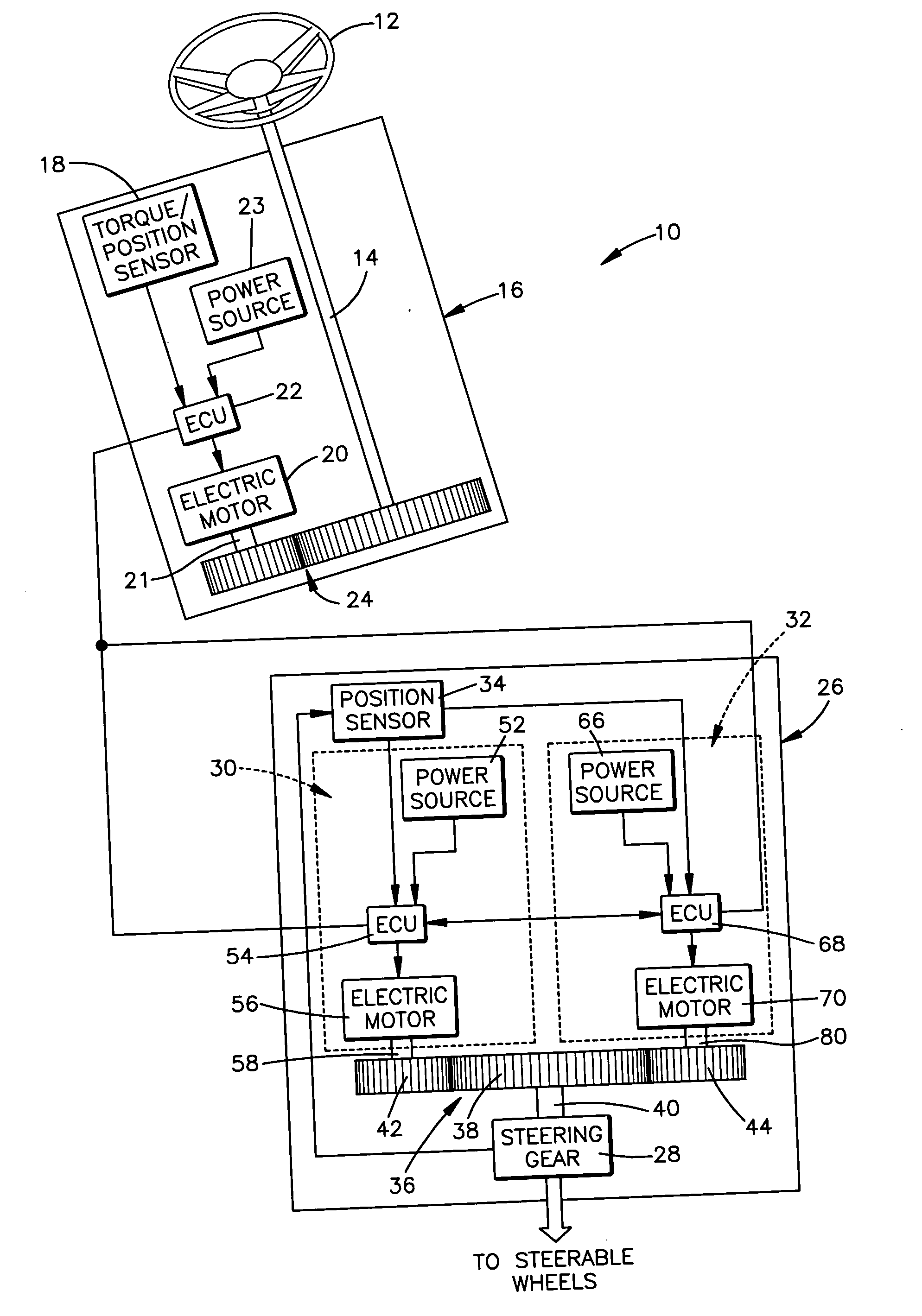
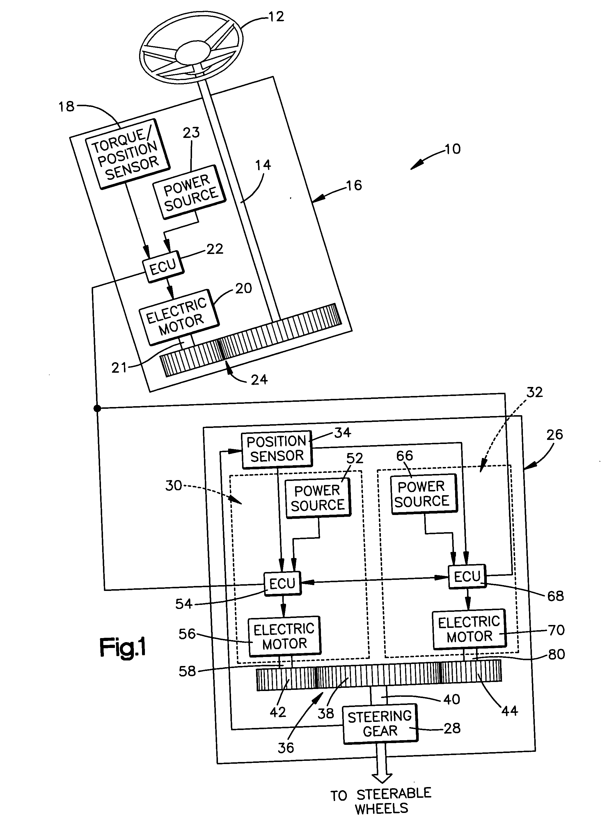
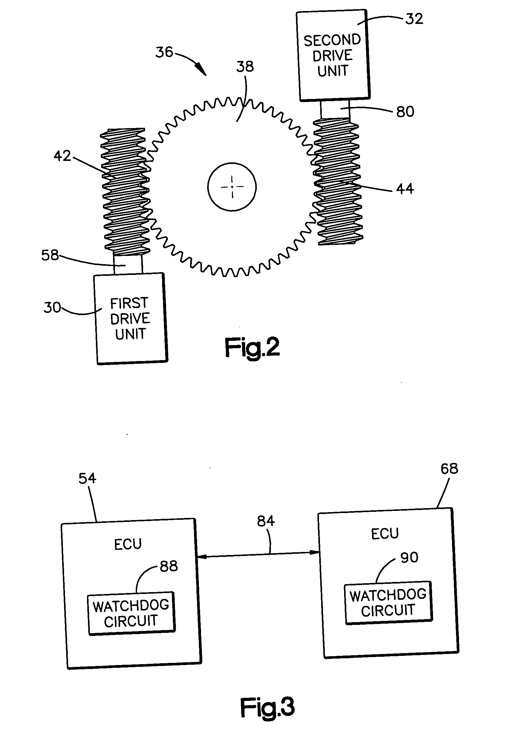
[0005] The present invention relates to a steering apparatus for turning steerable wheels of a vehicle in response to rotation of a steering wheel. The steering apparatus comprises a first assembly that is operatively coupled to the steering wheel and that includes components for sensing conditions of the steering wheel and for providing a control signal indicative of the sensed conditions. The steering apparatus also comprises a second assembly that includes a steering gear for, when actuated, turning the steerable wheels of the vehicle. The second assembly also includes first and second drive units. Each of the first and second drive units is operatively connected to an input shaft of the steering gear and is responsive to the control signal for actuating the steering gear. The second assembly has first and second modes of operation. The first and second drive units operate simultaneously in response to the control signal for actuating the steering gear when the second assembly is operating in the first mode of operation. Only one of the first and second drive units is operated in response to the control signal for actuating the steering gear when the second assembly is operating in the second mode of operation.
[0006] According to another aspect, the present i

Problems solved by technology

Routing the rigid shafts between the steering wheel and the steering gear is often difficult, as other vehicle components must not interfere with the shafts.
In a steer-by-wire system, a malfunction or failure of a portion of the second assembly may result in an inability to steer the vehicle.

Method used


Image

  • Steer-by-wire steering apparatus with redundant electric motor drive systems
  • Steer-by-wire steering apparatus with redundant electric motor drive systems
  • Steer-by-wire steering apparatus with redundant electric motor drive systems

Examples


Embodiment Construction

[0013]FIG. 1 schematically illustrates a vehicle steering apparatus 10 constructed in accordance with the present invention. The steering apparatus 10 includes a steering wheel 12. The steering wheel 12 is of known construction and is manually rotatable by a vehicle operator (not shown).

[0014] A shaft 14 is fixed to the center or hub of the steering wheel 12. Angular rotation of the steering wheel 12 results in an equivalent angular rotation of the shaft 14. The shaft 14 extends from the steering wheel 12 and into a first assembly 16.

[0015] The first assembly 16 is operatively coupled to the steering wheel 12 via the shaft 14. The first assembly 16 includes a torque / position sensor 18, a first electric motor 20, a first electronic control unit 22, and a first power source 23. The first assembly 16 is integrated into a single unit into which the shaft 14 extends.

[0016] The torque / position sensor 18 of the first assembly 16, shown schematically in FIG. 1, is operable to sense opera...


PUM


Abstract

A steering apparatus (10) includes first and second assemblies (16 and 26). The second assembly (26) includes a steering gear (28) and first and second drive units (30 and 32), each for actuating the steering gear (28). The second assembly (26) has first and second modes of operation. The first and second drive units (30 and 32) operate simultaneously for actuating the steering gear (28) when the second assembly (26) is operating in the first mode of operation. Only one of the first and second drive units (30 and 32) is operated when the second assembly (26) is operating in the second mode of operation.

Description

TECHNICAL FIELD [0001] The present invention relates to a steering apparatus for turning the steerable wheels of a vehicle in response to rotation of a vehicle steering wheel. More particularly, the present invention relates to a steer-by-wire steering apparatus for turning the steerable wheels of a vehicle. BACKGROUND OF THE INVENTION [0002] Power steering gears are common in modern vehicles. Typically, one or more rigid shafts connect a vehicle steering wheel to an input shaft of the power steering gear. The rigid shafts must be routed from the vehicle steering wheel to the input shaft of the power steering gear. Routing the rigid shafts between the steering wheel and the steering gear is often difficult, as other vehicle components must not interfere with the shafts. [0003] Some known vehicle steering systems have eliminated the rigid shafts. Such systems are commonly referred to as “steer-by-wire” systems. In steer-by-wire systems, there is no mechanical connection between the s...

Claims


Application Information

Patent Timeline
IPC IPC(8): B62D5/00
CPCB62D5/003B62D5/092B62D5/006
Inventor BOYLE, KEVIN E.SZABELA, WILLIAM A.
Owner TRW AUTOMOTIVE US LLC
Learn More