Bicarbonate container with two-channel plug-in connector for a hemodialysis apparatus

a hemodialysis apparatus and bicarbonate technology, applied in the field of bicarbonate containers, can solve the problems of high manufacturing cost, inconvenient positioning of the end of the hose in the bag,

Inactive Publication Date: 2006-03-02
RITTER FRANK
View PDF2 Cites 3 Cited by
  • Summary
  • Abstract
  • Description
  • Claims
  • Application Information

AI Technical Summary

Problems solved by technology

However, this arrangement requires relatively high manufacturing expenses and, more importantly, the end of the hose is not fixed so that, after filling the bag with bicarbonate, the end of the hose may not be in the most desirable position within the bag whereby the solution conducted through the bag flows only through part of the bicarbonate contained in the bag.

Method used


Image

  • Bicarbonate container with two-channel plug-in connector for a hemodialysis apparatus
  • Bicarbonate container with two-channel plug-in connector for a hemodialysis apparatus
  • Bicarbonate container with two-channel plug-in connector for a hemodialysis apparatus

Examples


first embodiment

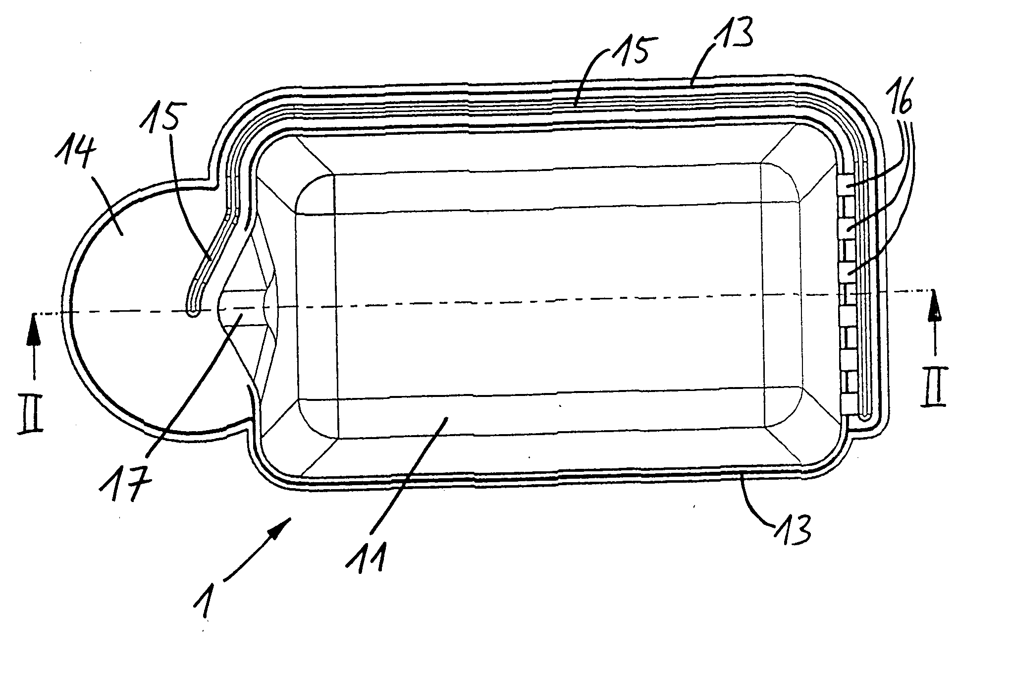
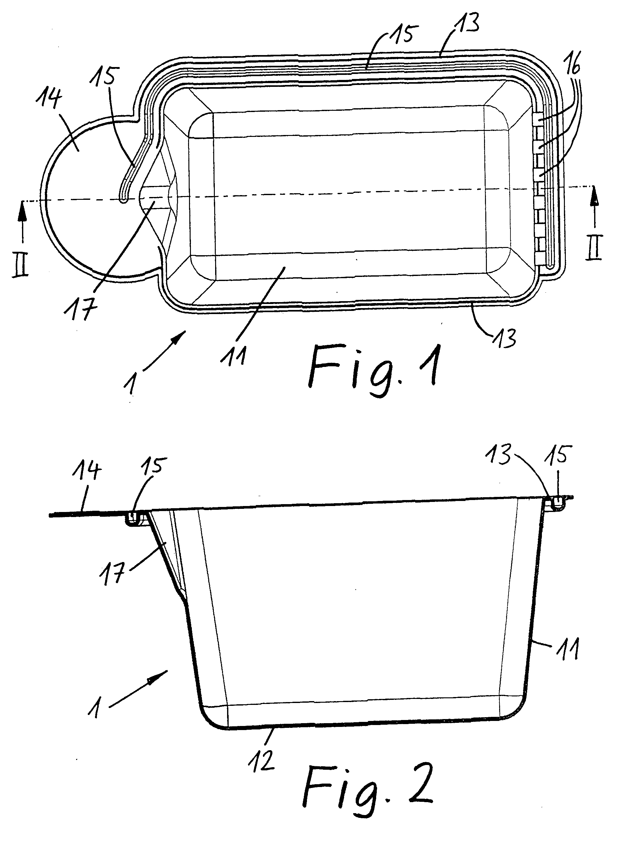
[0016] The bicarbonate container of the first embodiment as shown in FIGS. 1 to 5 comprises a bottom part 1 (FIGS. 1 and 2) and a cover part 2 (FIGS. 3 and 4), which is disposed on the bottom part 1 and welded thereto. Both parts are manufactured from plastic material by injection molding.

[0017] The bottom part 1 is in the form of a trough 11 with a bottom 12 and a top flange 13. The trough 11 has, in the embodiment shown, an essentially oblong shape with rounded corners and is slightly narrowing toward the bottom 12. However, the trough 19 could have any other shape, it could for example, be round or semispherical. The flange 13 is flat and extends in the top opening plane of the trough 11 that is around the top opening. The top side of the flange 13 forms a welding surface for welding a corresponding flange surface of the cover part 2 to the bottom part 1.

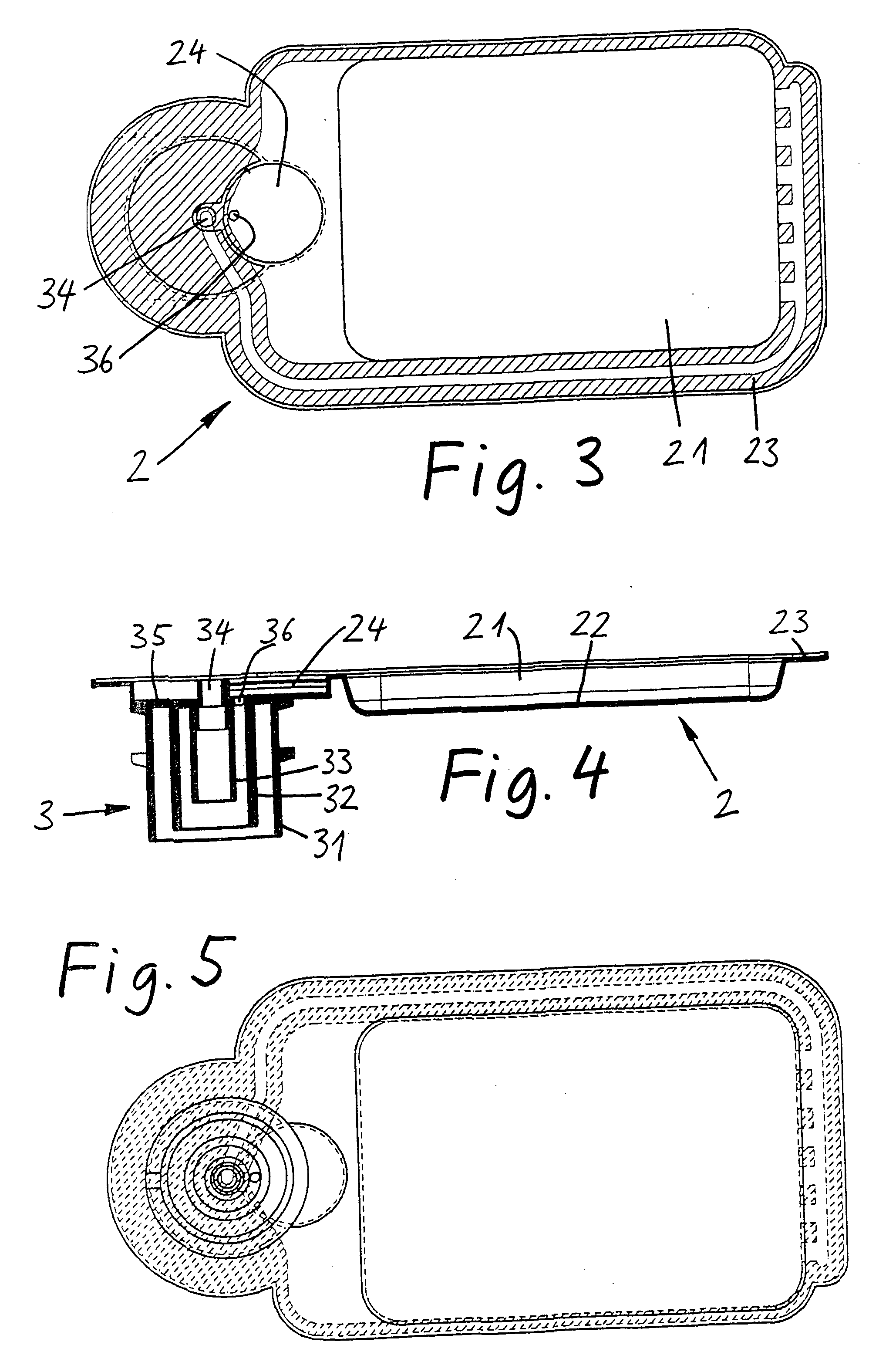
[0018] As shown in FIGS. 3 and 4, the cover part 2 is in the form of a flat tray 21 with a bottom 22 and a flat flange 23 exte...

second embodiment

[0028] The tubular conduit formed between the inner and the outer conductor bushings 33, 32 of the plug-in connector is again closed by a bottom wall 35 which has an opening 36, which, in the second embodiment, is in direct communication with the channel 25 formed into the flange 23.

[0029] Like in the first embodiment, the trough 11 of the bottom part 1 is provided also in the second embodiment with an outwardly projecting area 17, which in this case however is arranged at the end wall of the trough 11 opposite the plug-in connector 3. The channel 25 formed in the flange 23 of the cover part 2 is in communication with the area 17 formed by the outward projection by way of a flow transfer passage 27. As shown in FIG. 10 in an enlarged sectional view, the interior space of the projection 17 is separated from the interior space of the trough 11 by a filter disc 5 which extends between the trough 11 and the cover part 2 where it is retained by profile members 18 and, respectively, 28.

[...


PUM

PropertyMeasurementUnit
shapeaaaaaaaaaa
widthaaaaaaaaaa
areaaaaaaaaaaa

Abstract

In a bicarbonate container for one-time use with a hemodialysis apparatus which container consists of a bottom part with a trough for containing the bicarbonate, a cover for closing the trough and a two-channel plug-in connector for connection to a dialysis apparatus, the bottom part and the top part include flanges which are joined and form therebetween a conduit channel extending from one end of the container where the plug-in connector is disposed to the other end of the container for conducting liquid supplied through one of the plug-in connector channels through the bicarbonate filling of the trough of the container in which the bicarbonate is disposed to the other channel of the plug-in connector.

Description

BACKGROUND OF THE INVENTION [0001] The invention relates to a bicarbonate container for one time use in dialysis apparatus for hemodialysis that is a rigid plastic container including a two-channel plug-in connector for connection of the container to a dialysis apparatus. [0002] A bicarbonate container with a two-channel plug-in connector is already known from EP-0 575 970 A2, wherein the container is shown as a flexible bag. Since, because of the two-channel plug-in connector for the connection to a dialysis apparatus, the inlet and outlet for the solution circuit are disposed at the same location of the container, the container must include a conduit which extends within the container from one of the two plug-in connector channels to the opposite end of the container so that the solution can flow through the whole bicarbonate container. In the container disclosed in EP 0 575 970 A2, a flexible hose extends from one of the two plug-in connector channels through the interior of the ...

Claims


Application Information

Patent Timeline
Patent Type & Authority Applications(United States)
IPC IPC(8): B01D65/00
CPCA61M1/1656A61M1/1668A61M1/1666
Inventor RITTER, FRANK
Owner RITTER FRANK
Why Eureka
Try Eureka