Central fluid supply system with self-cleaning function for hemodialysis and working method thereof

A hemodialysis and self-cleaning technology, applied in dialysis systems, suction devices, etc., can solve problems such as polluting the environment, threatening the safety of dialysis patients, and cumbersome problems

Pending Publication Date: 2018-02-06
JIANGSU NAHAI BIOLOGICAL TECH CO LTD
View PDF0 Cites 2 Cited by
  • Summary
  • Abstract
  • Description
  • Claims
  • Application Information

AI Technical Summary

Problems solved by technology

Among them, physical high-temperature disinfection is convenient, simple, and has no residue. However, after the temperature at the end of the infusion line is easily attenuated below 80°C, it will cause incomplete disinfection of the infusion system; prolonged use of high-temperature disinfection will cause accelerated aging of the infusion line. The dust on the inner wall of the infusion pipeline will fall off, which will threaten the safety of

Method used


Image

  • Central fluid supply system with self-cleaning function for hemodialysis and working method thereof

Examples


Embodiment 1

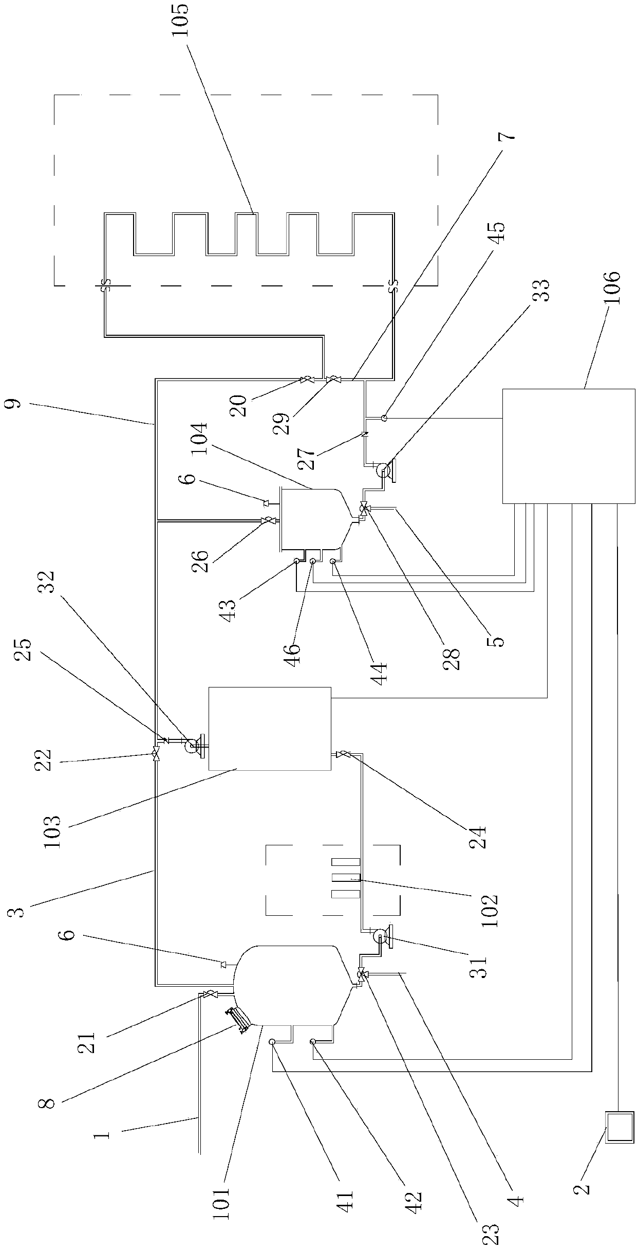
[0026] see figure 1 , figure 1 It is a structural schematic diagram of the online monitoring centralized liquid supply system of the present invention, including a control system 106 (single-chip microcomputer, central processing unit or PLC controller can be selected), a liquid crystal display 2, a remote monitoring server, a liquid distribution device, a disinfection device, a liquid storage device and An infusion pipeline 105 for connecting the liquid distribution device and the blood purification center.

[0027] The liquid distribution device includes a liquid distribution tank 101. The top of the liquid distribution tank 101 is provided with a water inlet 1 and a feeding port 8, which are used to feed dialysis water and required materials into the liquid distribution tank 101. Set the first valve 21 for controlling its on-off, the top of the liquid distribution tank 101 is also equipped with an ozone tail gas destroyer 6, which is used to eliminate the residual ozone in...

Embodiment 2

[0033] Taking the B concentrate in hemodialysis as an example, the working steps of the online monitoring centralized liquid supply system of the present invention are as follows:

[0034] A. The operation panel of the control system 106 selects the quantity and dilution ratio of the hemodialysis concentrate to be prepared, and controls the amount of water added for the corresponding dialysis water through the pressure sensor 42, and puts the hemodialysis B dry powder into the feeding port 8 of the liquid distribution tank 101, and passes through the machine Stir to completely dissolve the hemodialysis B dry powder, compare the conductivity of the concentrated solution through the conductivity sensor 42, confirm the ion concentration of the concentrated solution, and obtain qualified hemodialysis B concentrated solution, the first infusion pump 31 will pass the qualified blood The dialysis B concentrate flows through the filter 102 and the fourth valve 24 to reach the disinfect...


PUM


Abstract

The invention relates to a centralized liquid supply system for hemodialysis with self-cleaning function and a working method thereof, comprising a liquid dispensing device, a disinfection device, a liquid storage device and an infusion pipeline. The outlet end of the liquid device is connected to the inlet end of the ozone generator through the pipeline, the outlet end of the ozone generator is connected to the inlet end of the gas-liquid mixing pump through the pipeline, and the outlet end of the gas-liquid mixing pump is connected to the liquid storage device through the pipeline. The inlet end is connected, so that the concentrated liquid in the liquid dispensing device flows through the pipeline, the ozone generator, and the gas-liquid mixing pump to be mixed with the ozone generated by the ozone generator, and the outlet end of the liquid storage device is connected with the infusion pipeline through the pipeline. The outlet end of the gas-liquid mixing pump is connected with the inlet end of the liquid dispensing device through a return line that can be turned on and off, and the infusion line is connected with the outlet end of the liquid storage device through a return line that can be turned on and off.

Description

technical field [0001] The invention relates to the technical field of medical equipment, in particular to a centralized liquid supply system for hemodialysis with a self-cleaning function and a working method thereof. Background technique [0002] Hemodialysis (HD) is one of the renal replacement therapies for patients with acute and chronic renal failure. It drains the blood from the body to the outside of the body through a dialyzer composed of countless hollow fibers, and the blood and the electrolyte solution (dialysate) with a similar concentration to the body are exchanged through diffusion / convection inside and outside the hollow fibers , remove metabolic waste from the body, maintain electrolyte and acid-base balance; remove excess water from the body at the same time, and return the purified blood to the entire process called hemodialysis. [0003] During hemodialysis treatment, the hemodialysis machine dilutes A concentrated solution, B concentrated solution and ...

Claims


Application Information

Patent Timeline
IPC IPC(8): A61M1/16
CPCA61M1/1656A61M1/169
Inventor 钟禄丰
Owner JIANGSU NAHAI BIOLOGICAL TECH CO LTD
Why Eureka
Try Eureka