Conductivity measurement

A conductivity and frequency range technology, applied in the field of measurement systems, can solve problems such as fuzzy measurement values ​​and achieve improved measurement results

Active Publication Date: 2017-10-31
ROXAR FLOW MEASUREMENT
View PDF8 Cites 0 Cited by
  • Summary
  • Abstract
  • Description
  • Claims
  • Application Information

AI Technical Summary

Problems solved by technology

Thus, the measured value is ambiguous

Method used


Image

  • Conductivity measurement
  • Conductivity measurement
  • Conductivity measurement

Examples


Embodiment Construction

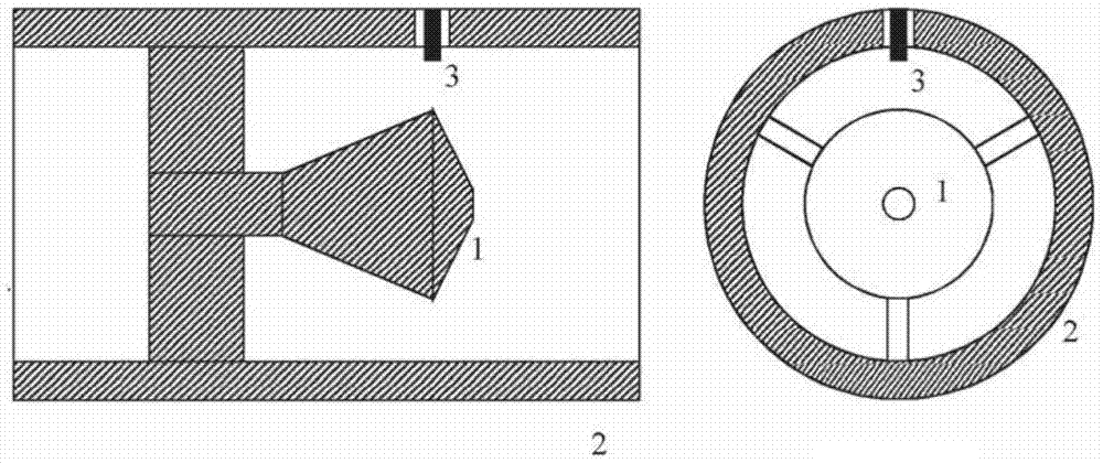
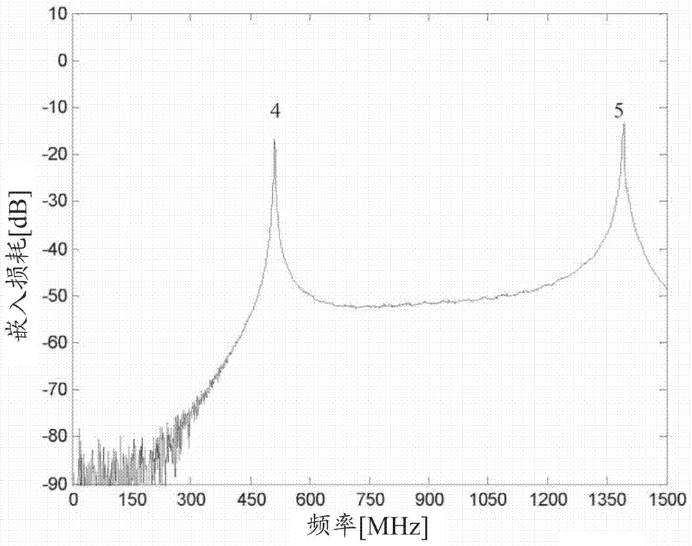
[0033] Figure 1a Shown is a conical insert 1 used as a resonator in a tube 2 comprising a coupling device 3 as discussed in WO2010 / 115883 above. The coupling device 3 can be configured as a probe, which is used to apply and / or induce an electromagnetic field in order to determine the resonance frequency and the Q-factor. Figure 1b The frequency response of a typical conical insert over a frequency range including the two resonant frequencies 4, 5 is shown. Typical tube diameters may be in the range of 50mm and 245mm, but this tube diameter may vary from case to case.

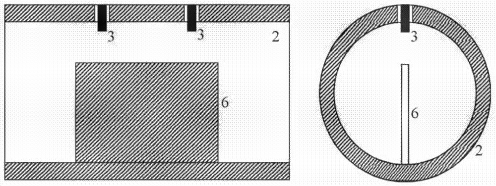
[0034] Figure 2a An alternative resonator consisting of fins 6 extending into the flow is shown. Figure 2b The two first resonance peaks are shown in this configuration based on an inner tube diameter of 146.4 mm and a fin length of approximately one tube diameter.

[0035] Various configurations are conceivable, as will be apparent to those skilled in the art. A flat, unobstructed tube has a single reso...


PUM


Abstract

The present invention relates to a system for measuring the conductivity of a multiphase fluid flow comprising a portion of water, the system comprising a measurement section comprising: Means for transmitting a signal into the tube containing said flow and means for detecting a resonant frequency in said range. The measurement section includes features for providing at least two resonant frequencies within the at least one frequency range, the system further comprising a Q factor based on at least the first resonant frequency and a first Q factor associated with the corresponding resonant peak, and a Q factor of the second resonant peak. Factor to calculate the conductivity of the water in the stream.

Description

technical field [0001] The invention relates to a measurement system for measuring properties of a fluid flow, in particular a multiphase fluid flow comprising a portion of water. Background technique [0002] In oil and gas production and processing, it is necessary to monitor the content and properties of the fluid streams because the oil, gas and water fractions and water salinity will change during production and affect further processing. Various types of techniques have been used to sample the information necessary to discover fractions and salinity, such as acoustic measurements, pressure, gamma rays, and electrical measurements. The invention relates to electrical measurements which are used to determine the content in mixtures of oil, gas and water, and in particular to determine the conductivity of water in a stream, thus indicating the salinity and / or water content in the stream . Dissolved salts in water make the water conductive. Conductivity depends on the a...

Claims


Application Information

Patent Timeline
Patent Type & Authority Patents(China)
IPC IPC(8): G01N33/28G01N22/00
CPCG01N33/2847G01F1/58G01F1/582G01N22/00
Inventor 埃伯·古斯塔夫·耐福斯
Owner ROXAR FLOW MEASUREMENT
Why Eureka
Try Eureka