Steering device for motor vehicle

Active Publication Date: 2006-03-02
NSK LTD
View PDF4 Cites 13 Cited by
  • Summary
  • Abstract
  • Description
  • Claims
  • Application Information

AI Technical Summary

Benefits of technology

[0010] It is an object of the present invention, which was devised under such circumstances, to provide a steering appara

Problems solved by technology

As a result, particularly in a telescopic structure requiring the elongate hole, a considerable degree of surface rigidity (flexural rigidity) of the periphery of the elongate hole at the swelling portion is not acquired, and a low level of the surface rigidity (flexural rigidity) of the swelling portion is a point that raises much concern.
Moreover, the peripheral edge of the elong

Method used


Image

  • Steering device for motor vehicle
  • Steering device for motor vehicle
  • Steering device for motor vehicle

Examples


Example

First Embodiment

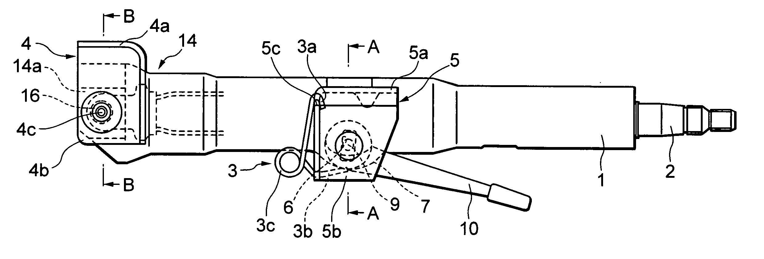
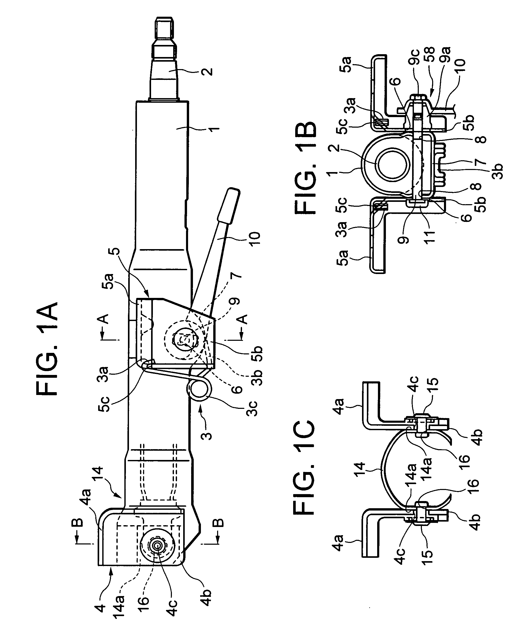
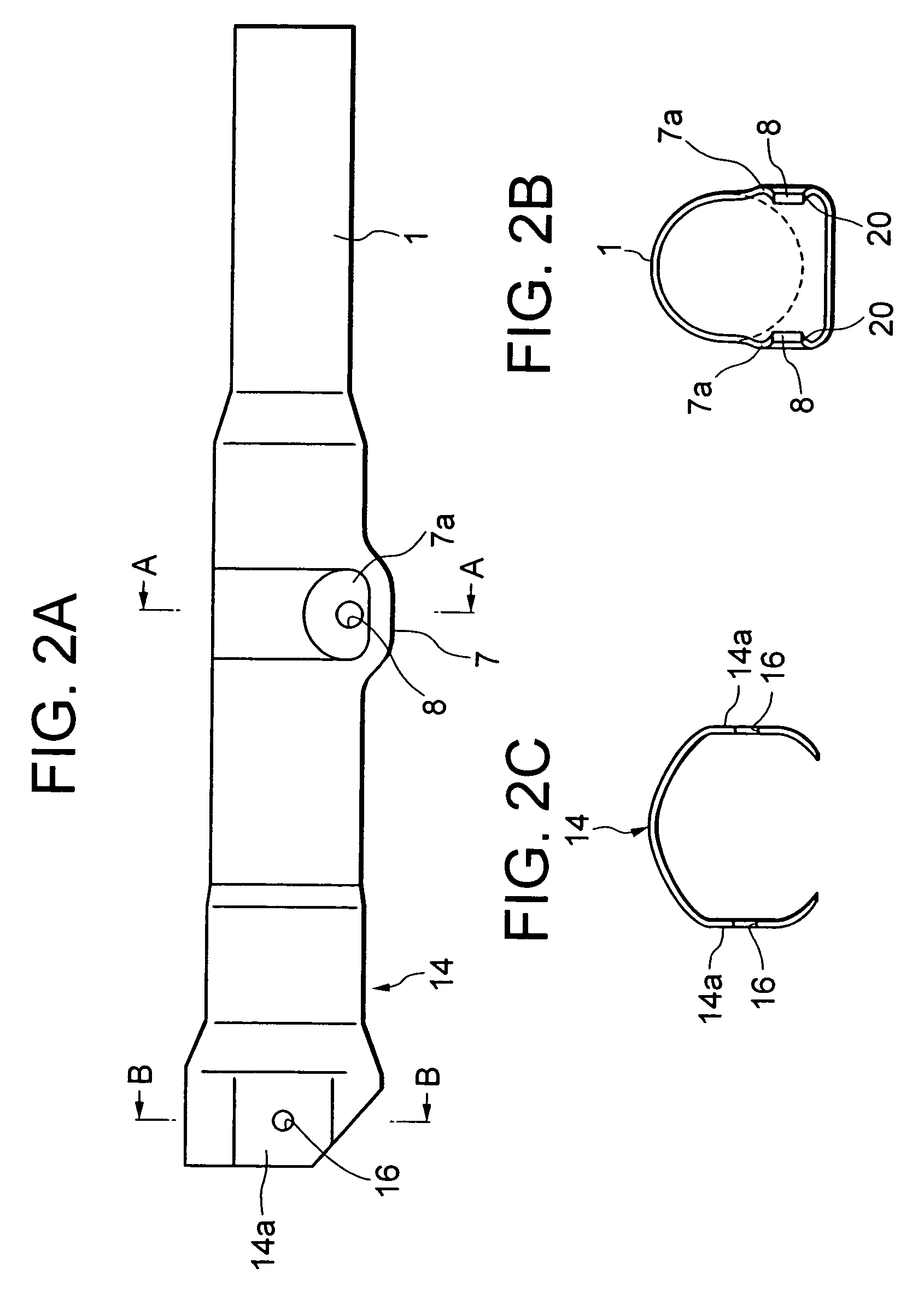
[0029]FIG. 1A is a side view of the whole of a tilt type steering column apparatus according to a first embodiment of the present invention. FIG. 1B is a sectional view taken along the line A-A in FIG. 1A, as well as being a sectional view of a steering column, of which a swelling portion takes an integral closed sectional structure, in the tilt type steering column apparatus for the vehicle according to the embodiment of the present invention. FIG. 1C is a sectional view taken along the line B-B in FIG. 1A, as well as being a sectional view of the steering column, of which a support bracket portion takes an integral closed sectional structure, in the tilt type steering column apparatus for the vehicle according to the embodiment of the present invention. FIGS. 2A, 2B and 2C are views each showing a structure of only a steering column 1 in FIGS. 1A, 1B, and 1C.

[0030] Referring to FIGS. 1A through 1C and FIGS. 2A through 2C, the tilt type steering apparatus for the ...

Example

Second Embodiment

[0046] Next, a steering column for a vehicle according to a second embodiment of the present invention will hereinafter be described.

[0047]FIG. 3A is a side view showing the whole of a tilt / telescopic position adjusting type steering column apparatus for the vehicle according to the second embodiment of the present invention. FIG. 3B is a sectional view taken along the line A-A in FIG. 3A, as well as being a sectional view of a steering column, wherein a swelling portion of the tilt / telescopic type steering column apparatus for the vehicle according to the second embodiment of the present invention takes an integral closed sectional structure. FIG. 3C is a sectional view taken along the line B-B in FIG. 3A, as well as being a sectional view of the steering column, wherein a support bracket portion of the tilt / telescopic type steering column apparatus for the vehicle according to the second embodiment of the present invention takes an integral closed sectional stru...

Example

Third Embodiment

[0059]FIG. 5 is a side view showing the whole of a tilt type steering column apparatus for the vehicle according to a third embodiment of the present invention. FIG. 6A is a sectional view taken along the line A-A in FIG. 5, as well as being a sectional view of a steering column, wherein a swelling portion of the tilt / telescopic type steering column apparatus for the vehicle according to the third embodiment of the present invention takes an integral closed sectional structure. FIG. 6B is a sectional view taken along the line B-B in FIG. 5, as well as being a sectional view of a support bracket portion of the tilt / telescopic type steering column apparatus for the vehicle according to the third embodiment of the present invention. FIG. 6C is a sectional view taken along the line C-C in FIG. 5, as well as being a sectional view of a steering column, wherein a swelling portion for fixing a harness of the tilt type steering column apparatus for the vehicle according to ...


PUM


Abstract

A steering apparatus for a vehicle has a steering column rotatably supporting a steering shaft, a first support member held between opposed flat plate portions of an upper bracket and supporting the steering column, a second support member held between opposed flat plate portions of a lower bracket and supporting the steering column, a first support mechanism for supporting the steering column on the upper bracket, and a second support mechanism for supporting the steering column on the lower bracket, wherein the steering column, the first support member and the second support member are integrally formed, the first support member is integrally formed with a first swelling portion having a pair of side portions that respectively press-abut on a pair of opposed flat plate portions of the upper bracket, and the second support member is integrally formed with a second swelling portion having a pair of side portions that respectively press-abut on a pair of opposed flat plate portions of the lower bracket.

Description

TECHNICAL FIELD [0001] The present invention relates to a steering apparatus for a vehicle. BACKGROUND ARTS [0002] In the prior art, a steering column integrally formed with a swelling portion is molded of a steel pipe by plastic working, etc., and side faces of the swelling portion are formed with round holes or elongate holes for adjusting a column position, through which a fastening bolt of a clamp mechanism is inserted. With this configuration, the swelling portion having the column position adjusting round holes or elongate holes takes a closed sectional structure integral with the steering column. Accordingly, the steering column itself can be given high rigidity, and it is possible to reduce manufacturing costs (a material cost, a working cost and an assembling cost) and a weight as well (e.g., Japanese Patent Application Laid-Open Publication No. 8-276852 and Japanese Patent Application Laid-Open Publication No. 10-7003). [0003] Note that the present applicant discloses, in ...

Claims


Application Information

Patent Timeline
IPC IPC(8): B62D1/18B62D1/16B62D1/184B62D1/189
CPCB62D1/16B62D1/189B62D1/184
Inventor SAWADA, NAOKIINOUE, KOJI
Owner NSK LTD
Why Eureka
Try Eureka