Link and producing method of the same

Inactive Publication Date: 2006-03-02
KOMATSU LTD
View PDF8 Cites 28 Cited by
  • Summary
  • Abstract
  • Description
  • Claims
  • Application Information

AI Technical Summary

Benefits of technology

[0025] As described above, according to the present invention, a link capable of lowering a level i

Problems solved by technology

When the link contacts a roller, such as a track roller, or an idler tumbler during driving of the crawler belt, the link butts against the roller or the i

Method used


Image

  • Link and producing method of the same
  • Link and producing method of the same
  • Link and producing method of the same

Examples


Embodiment Construction

[0033] Hereinafter, preferred embodiments of the present invention will be concretely described referring to the drawings.

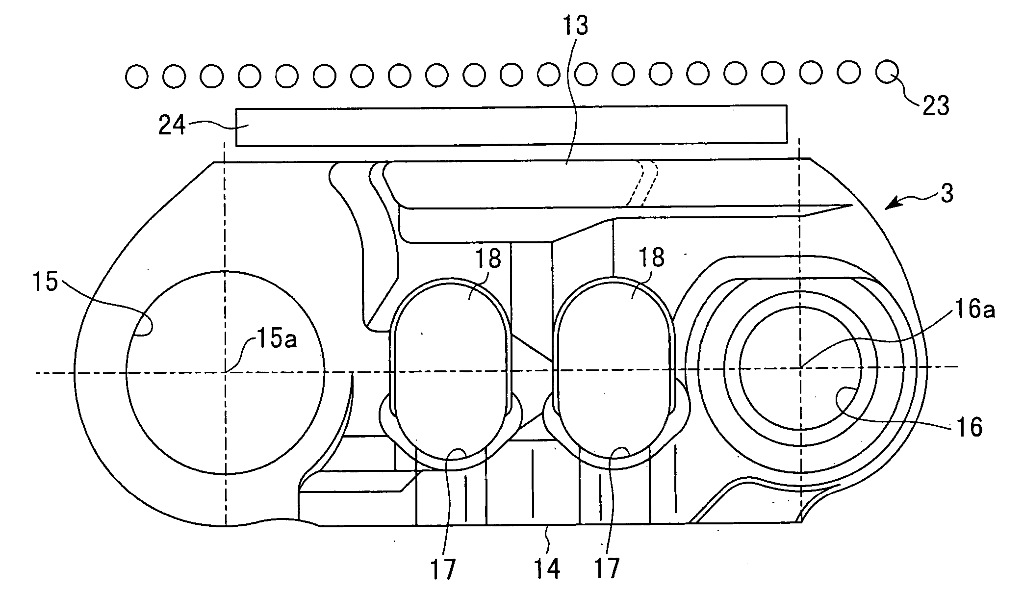
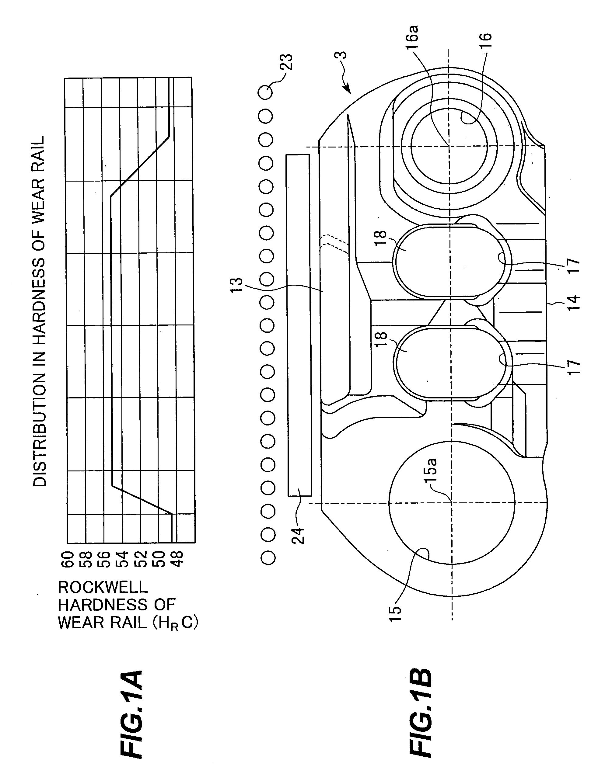
[0034]FIG. 1A is a graph showing a distribution in hardness of a wear rail of a link according to one embodiment of the present invention, and FIG. 1B is a side view showing the link equipped with a wear rail having the distribution in hardness showing in FIG. 1A. In the link according to this embodiment, the same parts as those of a conventionally used link are represented by the same numbers and explanations thereof are omitted.

[0035] In a track-type work machine, a crawler belt 1 is elliptically winded around a sprocket wheel 7, an idler tumbler 6 and track rollers 8, as shown in FIG. 5. The crawler belt 1 is composed of a crawler chain constructed such that a plural of links 3 are endlessly interlinked at ends thereof by connecting pins 4, in which a shoe plate 2 is fixed to one surface of each of the links. And, as shown in FIG. 1B, the link 3 is formed wi...


PUM

PropertyMeasurementUnit
Temperatureaaaaaaaaaa
Widthaaaaaaaaaa
Hardnessaaaaaaaaaa

Abstract

A link has link connecting bores (15) and (16) at both ends thereof and a wear rail (13) disposed between the upper portions of the link connecting bores (15) and (16). Portions near the ends of the wear rail (13) are designed to have hardness smaller than that of a center portion of the wear rail. Accordingly, the portions near the ends of the wear rail can be abraded easier than the center portion of the wear rail. Since the portions near the ends of the wear rail, in which the portions are easily abraded, are positioned closer to the link connecting bores, abrasion loss in use is smaller than that of the center portion owing to its structure. So, the difference in abrasion amount makes it possible to lower a level irregularity of the wear rail.

Description

FIELD OF THE INVENTION [0001] The present invention relates to a link constituting a crawler belt equipped for a track-type work machine and a producing method of the same. More particularly, the present invention relates to a link capable of lowering a level irregularity of a wear rail of the link owing to abrasion and a producing method of the same. BACKGROUND OF THE INVENTION [0002]FIG. 5 is a side view showing a structure of a running gear equipped with a link. [0003] A track-type work machine is equipped with a pair of running gears 10, shown in FIG. 5, at the right and left sides of the lower part thereof. The running gear 10 has a crawler belt 1. The crawler belt 1 is constructed such that a plural of links 3 are circularly interlinked by connecting pins 4, in which a shoe plate 2 is fixed to each of the links 3 by a bolt. [0004] The running gear 10 is provided with a track frame 5 disposed in the longitudinal direction of the work machine, and an idler tumbler 6 and a sprock...

Claims


Application Information

Patent Timeline
IPC IPC(8): B65G23/06
CPCB62D55/21B62D55/20
Inventor SHO, TOMOYOSHIYAMASHITA, TATSUO
Owner KOMATSU LTD
Why Eureka
Try Eureka