Thermoelectric Conversion System and of Increasing Efficiency of Thermoelectric Conversion System

a conversion system and thermoelectric technology, applied in the manufacture/treatment of thermoelectric devices, electrical apparatus, generators/motors, etc., can solve the problems of increasing the utilization of waste heat, the possibility of exceeding the maximum working temperature melting of joining materials, etc., to achieve low emissivity, reduce the quantity of heat input, and maintain the soundness of the thermoelectric conversion module

Inactive Publication Date: 2008-01-31
CENTRAL RESEARCH INSTITUTE OF ELECTRIC POWER INDUSTRY +1
View PDF6 Cites 43 Cited by
  • Summary
  • Abstract
  • Description
  • Claims
  • Application Information

AI Technical Summary

Benefits of technology

[0018] According to the thermoelectric conversion system and the efficiency improving method of the thermoelectric conversion system of the present invention, the system comprises the heat receiving surface having adequate a plurality of emissivities according to the quantity of heat received from the heat source. Thus, it is possible to limit the quantity of the heat input to the thermoelectric conversion module to the maximum working temperature or less, keep soundness of the thermoelectric conversion module and actuate the thermoelectric conversion module at a temperature as close to the maximum working temperature as possible. To be more specific, even in an area of a heat source temperature exceeding the maximum working temperature on the heat receiving surface covered with black bodies, low emissivity is set so that the heat receiving surface can become less heatable so as to limit a heating temperature of the thermoelectric conversion module to the maximum working temperature or less and keep soundness of the thermoelectric conversion module. At the same time, on the heat receiving surface for receiving a small quantity of heat from the heat source, high emissivity is set so that the heat receiving surface can become more heatable so as to keep the heating temperature of the thermoelectric conversion module close to the maximum working temperature and attain high power generation efficiency by increasing the temperature difference between the heat receiving surface and the cooling surface. Thus, the thermoelectric conversion system can increase utilization of the waste heat and attain a large power generation quantity so as to improve its economic efficiency.
[0019] According to the thermoelectric conversion system of the present invention, it is further possible to select the emissivity appropriately out of a variety of materials by selecting the materials and covering materials configuring the heat receiving surface or adjusting the surface roughness of the heat receiving surface or the like. In the case where the material of a required emissivity is nevertheless unavailable, it is possible to easily adjust the emissivity of the heat receiving surface to the optimal value, limit the quantity of the heat input to the thermoelectric conversion module to the maximum working temperature or less, keep soundness of the thermoelectric conversion module and actuate the thermoelectric conversion module at a temperature as close to the maximum working temperature as possible.
[0020] Furthermore, the heat receiving surface of the thermoelectric conversion system of the present invention can obtain an arbitrary emissivity by combining materials or covering materials having different emissivities or selecting the surface roughness. Therefore, it is possible to have different emissivities on the entire heat receiving surface or in part of one heat receiving surface. The emissivity of the entire heat receiving surface is almost equal to an average of the emissivities of the materials configuring the heat receiving surface, and a target emissivity can be obtained even in the case where the material of a required emissivity is not available. As the heat receiving surface of the present invention is formed by regularly arranging the combinations of a plurality of materials, covering materials and the like, irregularity of the emissivity is reduced on the entire heat receiving surface. Furthermore, the heat receiving surface of the present invention has unit sizes of the materials, covering materials and surface roughness having different emissivities to be combined, smaller than area of the thermoelectric element contacting the heat receiving surface. Therefore, there are no variations in temperature chip by chip of a thermoelectric semiconductor.
[0021] Furthermore, the thermoelectric conversion system according to the present invention comprises the thermoelectric elements having different operative temperatures according to the quantity of heat received from the heat source in conjunction with optimization of the emissivity. Therefore, it is possible to prevent the thermoelectric conversion module from exceeding an upper limit of the working temperature against a higher-temperature heat source and keep the heating temperature of the thermoelectric conversion module close to the maximum working temperature against a lower-temperature heat source so as to actuate the thermoelectric conversion module with higher power generation efficiency.
[0022] Furthermore, the thermoelectric conversion system can perform efficient power generation by utilizing the waste heat generated in the cooling zone of the sintering furnace, which allows practical application of the power generation utilizing the waste heat generated in the cooling zone of the sintering furnace.

Problems solved by technology

Thus, there is a problem that it is impossible to strike a balance between increasing utilization of waste heat and increasing output of power generation.
Depending on the heat source temperature, however, there is a possibility that a maximum working temperature of the thermoelectric conversion module may be exceeded.
For this reason, if the thermoelectric conversion module is heated over the maximum working temperature of the thermoelectric conversion module 100, there is a possibility that the joining material melts and the thermoelectric conversion module gets damaged.
Therefore, an output difference per thermoelectric conversion module between upstream and downstream of the cooling zone is very large.
Therefore, use of the waste heat is not efficient enough, which is not desirable in view of reduction in equipment cost and unit cost of power generation.
Thus, it has been difficult to construct a power generating system so as to obtain maximum output with the thermoelectric conversion module by using as the heat source the waste heat generated by the industrial furnace having the cooling zone involving the waste heat such as a sintering furnace.
In the case where a quantity of heat received from the heat source is not even on the entire heat receiving surface of the thermoelectric conversion module, however, there is a problem that power generation efficiency deteriorates at a low-temperature location if the thermoelectric conversion system is constructed according to the maximum temperature, and the thermoelectric conversion module gets damaged at a high-temperature location if the thermoelectric conversion system is constructed according to the minimum temperature.

Method used


Image

  • Thermoelectric Conversion System and of Increasing Efficiency of Thermoelectric Conversion System
  • Thermoelectric Conversion System and of Increasing Efficiency of Thermoelectric Conversion System
  • Thermoelectric Conversion System and of Increasing Efficiency of Thermoelectric Conversion System

Examples


example

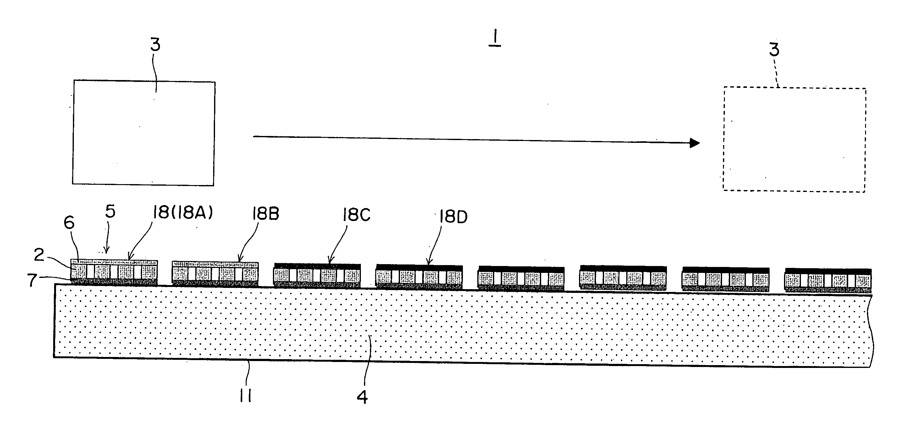
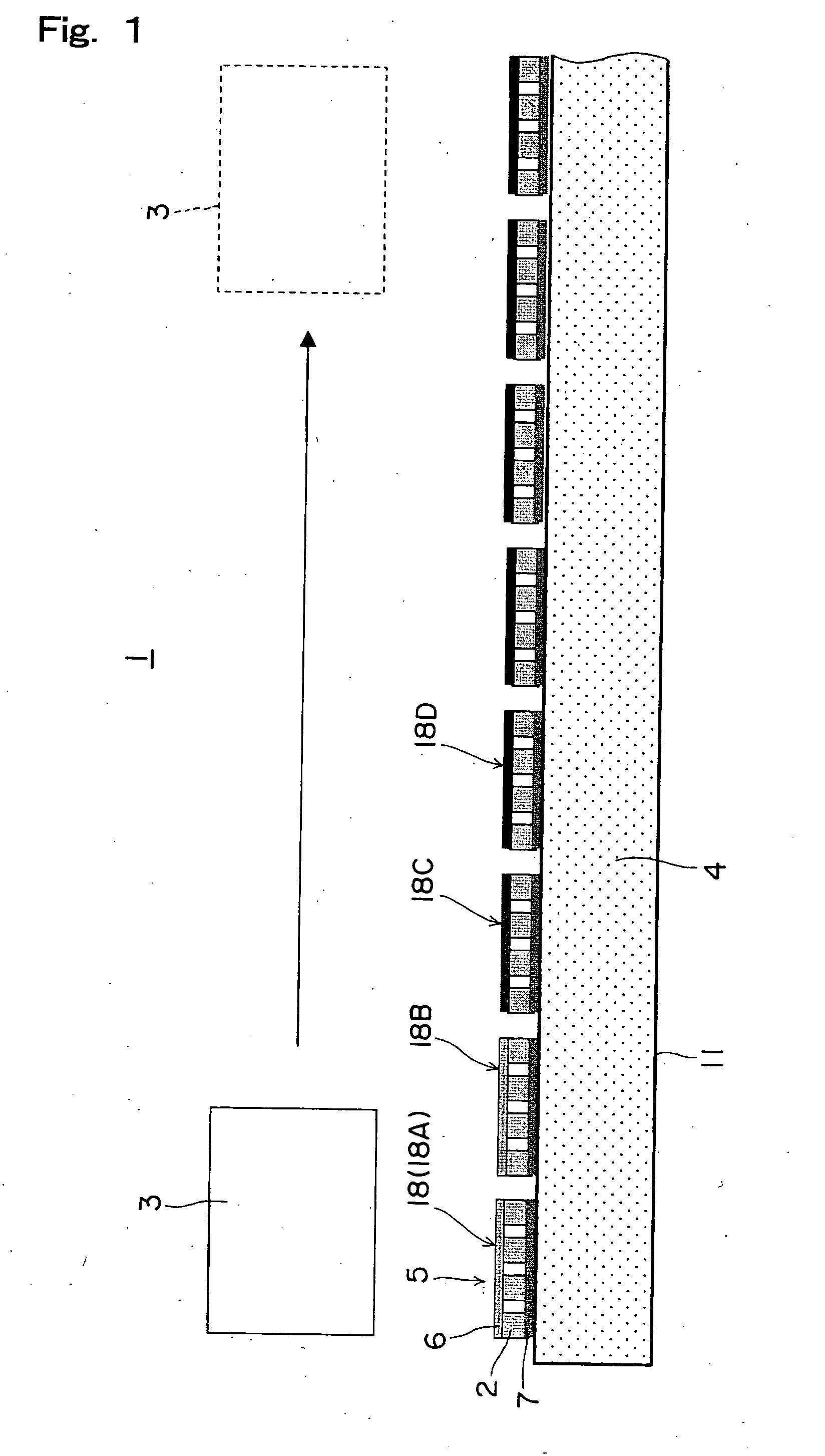
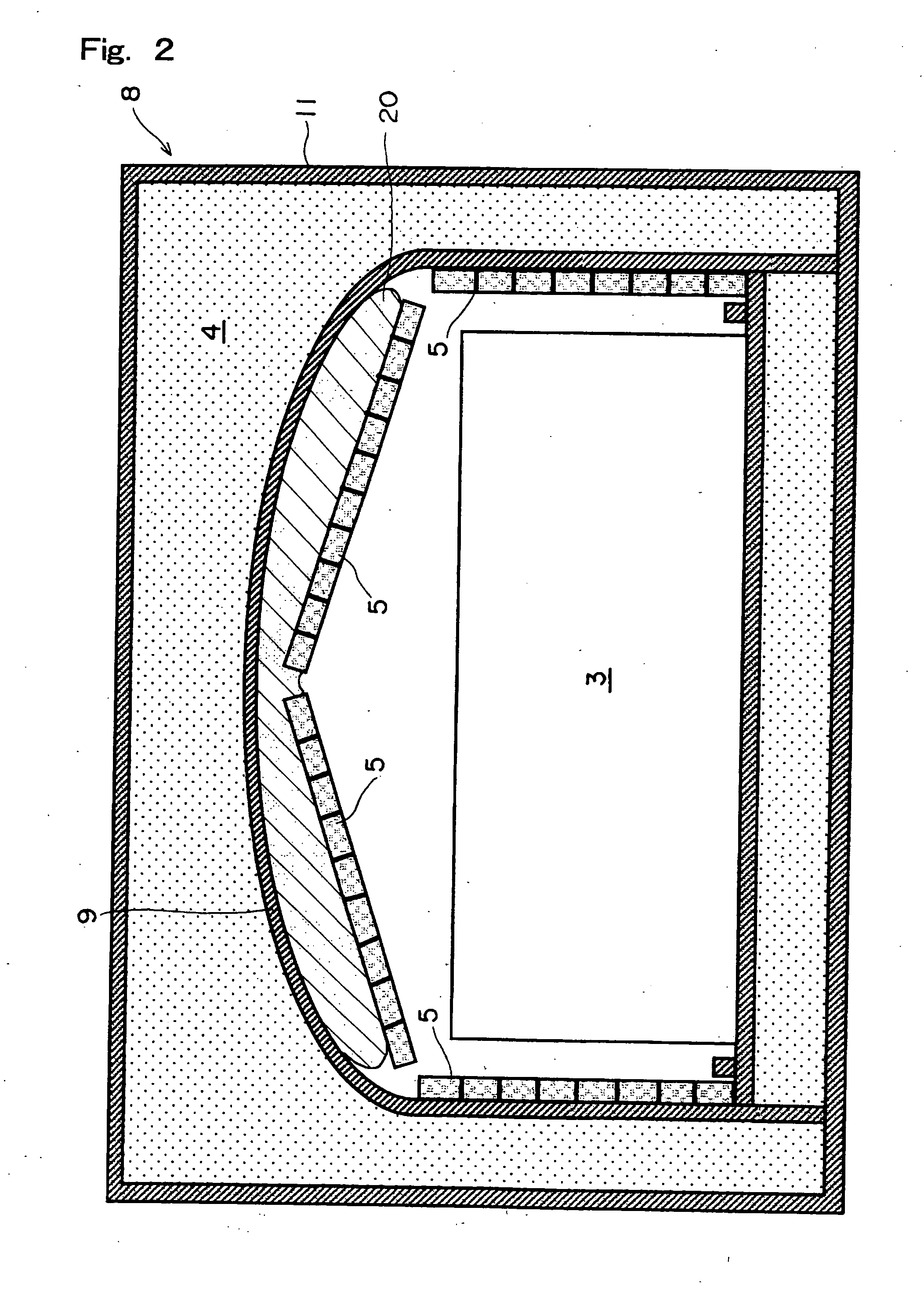
[0078] A plurality of thermoelectric conversion modules 5 were installed along the movement path of the work 3 inside the muffle 9 in the cooling zone 9c of the sintering furnace 8 shown in FIGS. 1 to 4. The axial length L1 of the preheat zone 9a of the sintering furnace 8 is 3 m, the axial length L2 of the sintering zone 9b is 4 m, and the axial length L3 of the cooling zone 9c is 8 m. As shown in FIG. 4, the work (graphite box) 3 heated by the preheat zone 9a and sintering zone 9b is at 100° C. at the outlet of the sintering zone 9b, that is, the inlet of the cooling zone 9c. It is assumed that a main stream temperature of cooling water as the coolant 4 is 30° C. almost constantly. The reduction atmosphere is inside the muffle 9 of the cooling zone 9c. The thermoelectric elements of which maximum working temperature is 550° C. were used as the thermoelectric conversion modules 5, and the installation range L4 of the thermoelectric conversion modules 5 was 2.5 m from the inlet of t...


PUM


Abstract

The present invention relates to a thermoelectric conversion system for receiving heat by radiation from a heat source and an efficiency improving method of the thermoelectric conversion system, the system including at least one thermoelectric conversion module 5 having at least a pair of thermoelectric elements 2, a heat receiving zone 6 placed not to contact a heat source 3 for receiving heat by radiation from the heat source 3 and a radiating zone 7 positioned on an opposite side to the heat receiving zone 6 and cooled by a coolant 4, generating electric power by a temperature difference between the heat receiving zone 6 and the radiating zone 7, a continuous or divided heat receiving surface 18 formed by one or a plurality of surfaces facing the heat source 3 of the heat receiving zone 6, and each of the heat receiving surface 18 is given a different quantity of heat from the heat source 3, the system comprising the heat receiving surface 18 has a plurality of different emissivities according to the quantity of heat received from the heat source 3.

Description

TECHNICAL FIELD [0001] The present invention relates to a thermoelectric conversion system for receiving heat by radiation from a heat source and an efficiency improving method of the thermoelectric conversion system. To describe it further in detail, the present invention relates to the thermoelectric conversion system suitable for use as a thermoelectric conversion system of which heat source is waste heat generated by a sintering furnace, iron or non-ferrous metal manufacturing plants and the like and the efficiency improving method of the thermoelectric conversion system. BACKGROUND ART [0002] There is conventionally a proposal of a power generating system for generating electric power with a thermoelectric conversion module by utilizing waste heat generated by an industrial furnace (Patent Document 1). This power generating system is the one wherein a cooling plate as a heat receiving surface on a low-temperature side of the thermoelectric conversion module is attached on a bul...

Claims


Application Information

Patent Timeline
Patent Type & Authority Applications(United States)
IPC IPC(8): H01L35/30H01L35/32H01L35/34H02N11/00
CPCH01L35/30H02N11/002H01L35/34H01L35/32H10N10/01H10N10/17H10N10/13H02N11/00
Inventor KAMBE, MITSURUSHIKATA, HIDEO
Owner CENTRAL RESEARCH INSTITUTE OF ELECTRIC POWER INDUSTRY
Why Eureka
Try Eureka