
Variable length decoding device

Active Publication Date: 2006-03-02
PANASONIC SEMICON SOLUTIONS CO LTD
View PDF4 Cites 4 Cited by
  • Summary
  • Abstract
  • Description
  • Claims
  • Application Information

AI Technical Summary

Benefits of technology

[0023] Therefore, a main object of the present invention is to provide a variable length decoding method and a variable length decoding device capable of dispensing with the initialization of a data buffer and achieving a high efficiency by shortening a processing time in a read operation.

Problems solved by technology

The disadvantage resulted in the generation of an idle period, which was unfavorably an impediment in achieving a higher-speed operation.
Further, the idle time generated between the decoding process and the read operation and the number of accesses with respect to the data buffer could not be disadvantageously reduced because all of the data was necessarily read from the data buffer.

Method used


Image

  • Variable length decoding device
  • Variable length decoding device
  • Variable length decoding device

Examples


first preferred embodiment

[0192] A variable length decoding device according to a first preferred embodiment of the present invention is described referring to the drawings.

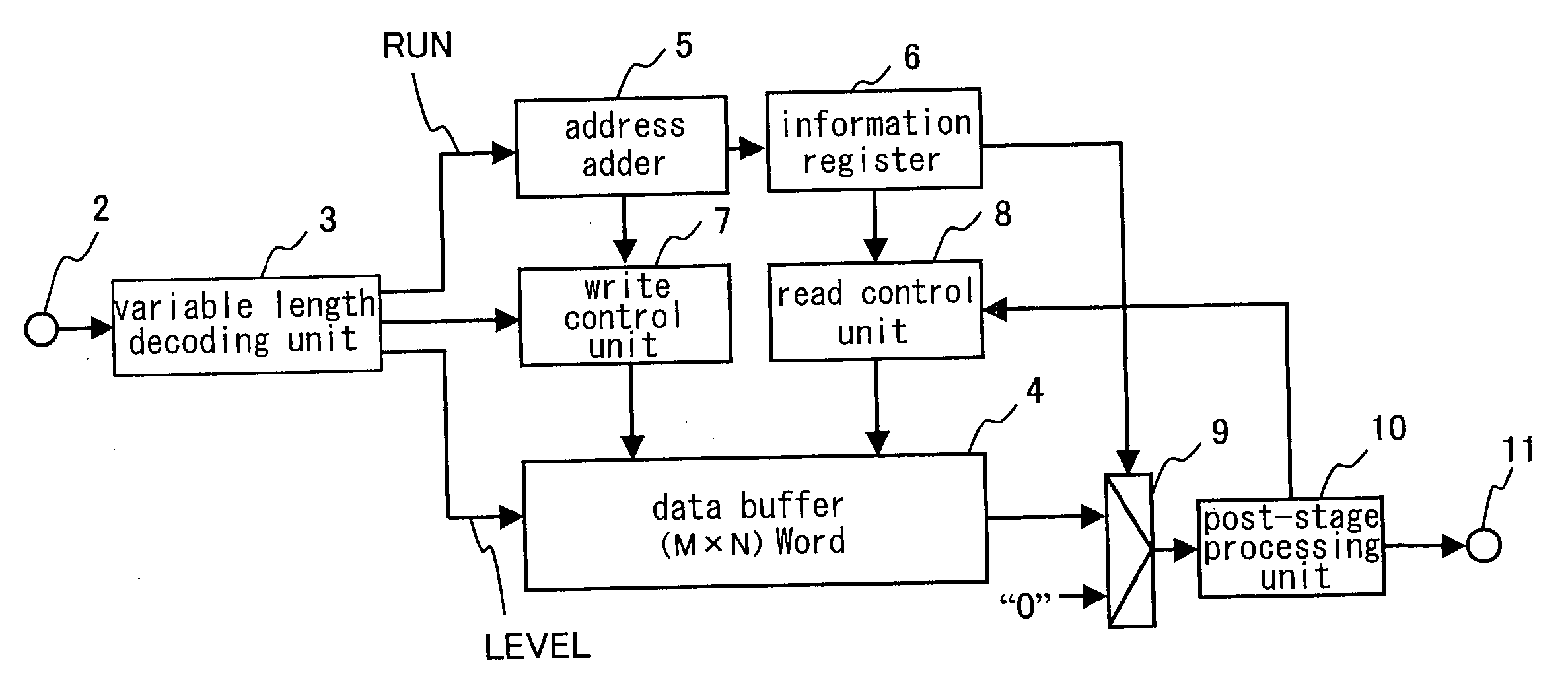
[0193]FIG. 1 shows a schematic constitution of a variable length decoding device according to the first preferred embodiment. The present embodiment is described referring to a case in which one block includes 8×8 number of data.

[0194] Referring to reference numerals in FIG. 1, 2 denotes an input unit for inputting variable length coding / run length coding data, 3 denotes a variable length decoding unit for serially decoding the data inputted from the input unit 2 in a state in which “RUN” representing number of “0” and “LEVEL” representing a magnitude of a coefficient value are combined, 4 denotes a data buffer for storing the “LEVEL”, 5 denotes an address adder for calculating an address of the “LEVEL” corresponding to the “RUN” based on the number of “0” indicated by the “RUN”, 6 denotes an information register of m×n bits for memoriz...

second preferred embodiment

[0213] A variable length decoding device according to a second preferred embodiment of the present invention is described referring to the drawings.

[0214]FIG. 8 shows a schematic constitution of the variable length decoding device according to the second preferred embodiment. Any component shown in FIG. 8, which is constituted in a similar manner as in the first preferred embodiment, is indicated by the same numeral and not described here again.

[0215] The variable length decoding device according to the present embodiment is constituted in such manner that the data buffer 4 is adapted to store the two “LEVEL” from the variable decoding unit 3 at one address, and a second selecting unit 14 for selecting the data outputted from the data buffer 4 is further provided in the constitution of the variable length decoding device according to the first preferred embodiment.

[0216] An operation of the variable length decoding device according to the present embodiment is described referring...

third preferred embodiment

[0223] A variable length decoding device according to a third preferred embodiment of the present invention is described referring to the drawings.

[0224]FIG. 11 shows a schematic constitution of the variable length decoding device according to the third preferred embodiment. Any component shown in FIG. 11, which is constituted in a similar manner as in the first preferred embodiment, is indicated by the same numeral and not described here again.

[0225] The variable length decoding device according to the present embodiment is constituted in such manner that a second data buffer 15, a second write control unit 16 and a second read control unit 17 are further provided in the constitution of the variable length decoding device according to the first preferred embodiment.

[0226] An operation of the variable length decoding device according to the present embodiment is described referring to the drawings. The present embodiment is described referring to the case in which one block inclu...


PUM


Abstract

A variable length decoding device for decoding variable length coding data and run length coding data according to the present invention comprises a variable length decoding unit 3 for serially decoding the variable length coding data and the run length coding data inputted from outside in a state in which “RUN” representing number of “0” and “LEVEL” representing a magnitude of a coefficient value are combined, a data buffer 4 for storing the “LEVEL”, address retainers 5 and 6 for retaining an address of the “LEVEL” corresponding to the “RUN” based on the number of “0” indicated by the “RUN”, a write control unit 7 for writing the “LEVEL” in the data buffer 4 based on the information of the address retainers, and a read control unit 8 for reading the “LEVEL” from the data buffer 4 based on the information of the address retainers.

Description

FIELD OF THE INVENTION [0001] The present invention relates to a decoding method and a decoding device for executing a variable length decoding and a run length decoding to code data in which a run length coding and a variable length coding are used, more particularly to a variable length decoding method and a variable length decoding device used in an image extension technology for extending compressed image data. The present invention further relates to an image pickup system. BACKGROUND OF THE INVENTION [0002] A method of compressing / extending compressed data using a run length coding and a variable length coding is used in JPEG (Joint Photographic Experts Group) and MPEG (Moving Picture Experts Group), which are general technologies for compressing image data. Along with the spread of a digital camera and a digital video camera and the advancement of the communication technology, the method has been made widely available as a technology capable of transferring data with a small ...

Claims


Application Information

Patent Timeline
IPC IPC(8): H03M7/46H03M7/40H04N19/00H04N19/102H04N19/134H04N19/189H04N19/423H04N19/44H04N19/625H04N19/91H04N19/93
CPCH03M7/40
Inventor TAKAKURA, KENTAROKITAMURA, SHINJINAGATA, TAICHI
Owner PANASONIC SEMICON SOLUTIONS CO LTD
Learn More