RFID device with magnetic coupling

a magnetic coupling and rfid technology, applied in loop antennas, electrical apparatus construction details, instruments, etc., can solve the problems of large area reducing the accuracy required for placement of ics during manufacture, and serious limitations in high-speed manufacturing of ic placement and mounting

Inactive Publication Date: 2006-03-02
AVERY DENNISON CORP
View PDF21 Cites 126 Cited by
  • Summary
  • Abstract
  • Description
  • Claims
  • Application Information

AI Technical Summary

Problems solved by technology

The larger area reduces the accuracy required for placement of ICs during manufacture while still providing effective electrical connection.
IC placement and mounting are serious limitations for high-speed manufacture.
Another problem to be solved in producing inlays using interposers is the reliable high speed mechanical and electrical coupling of the interposers (and interposer leads) to antennas.

Method used


Image

  • RFID device with magnetic coupling
  • RFID device with magnetic coupling
  • RFID device with magnetic coupling

Examples


Embodiment Construction

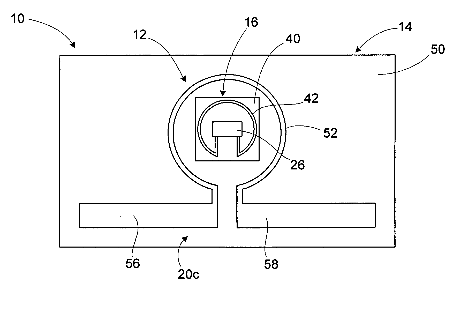
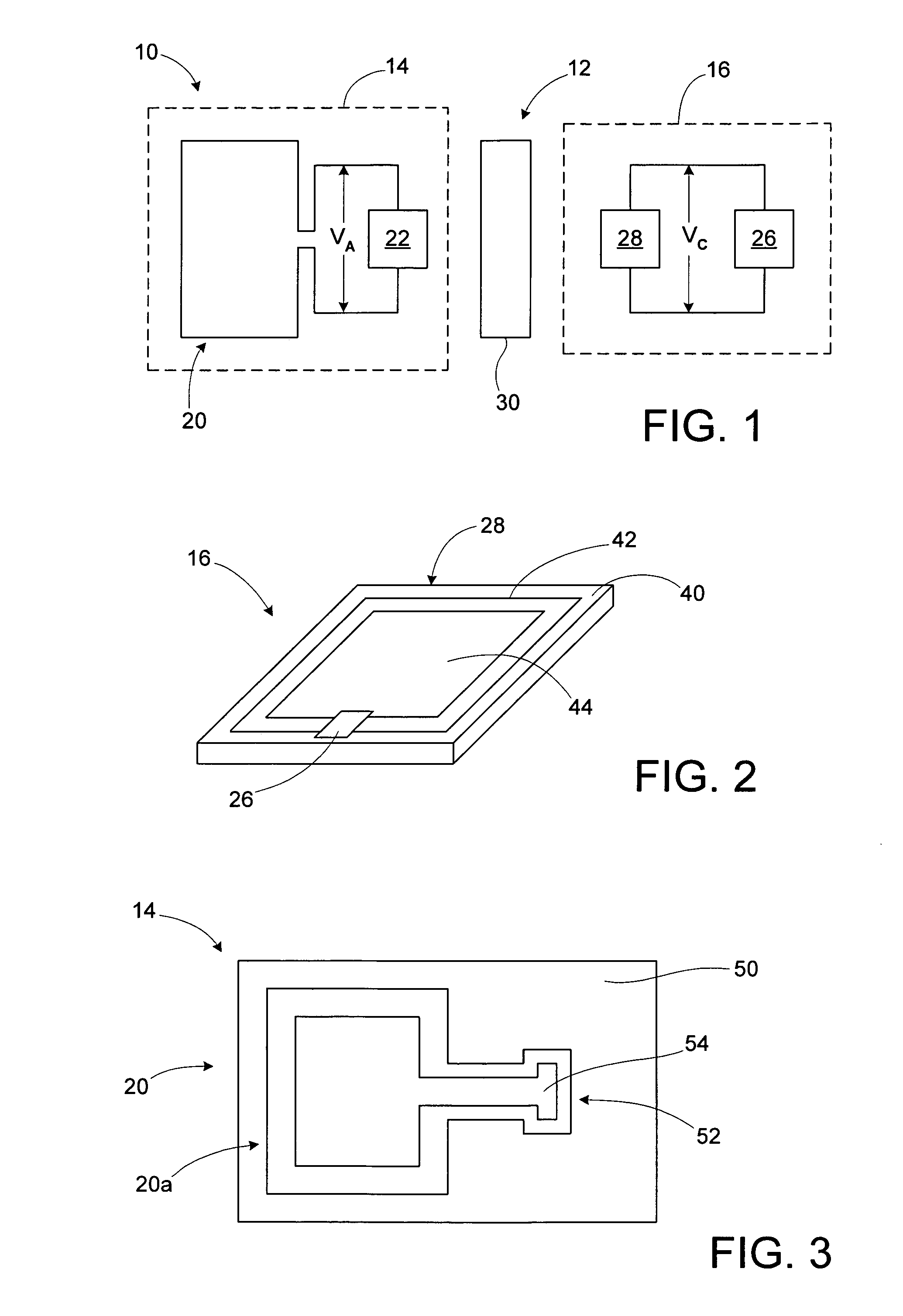
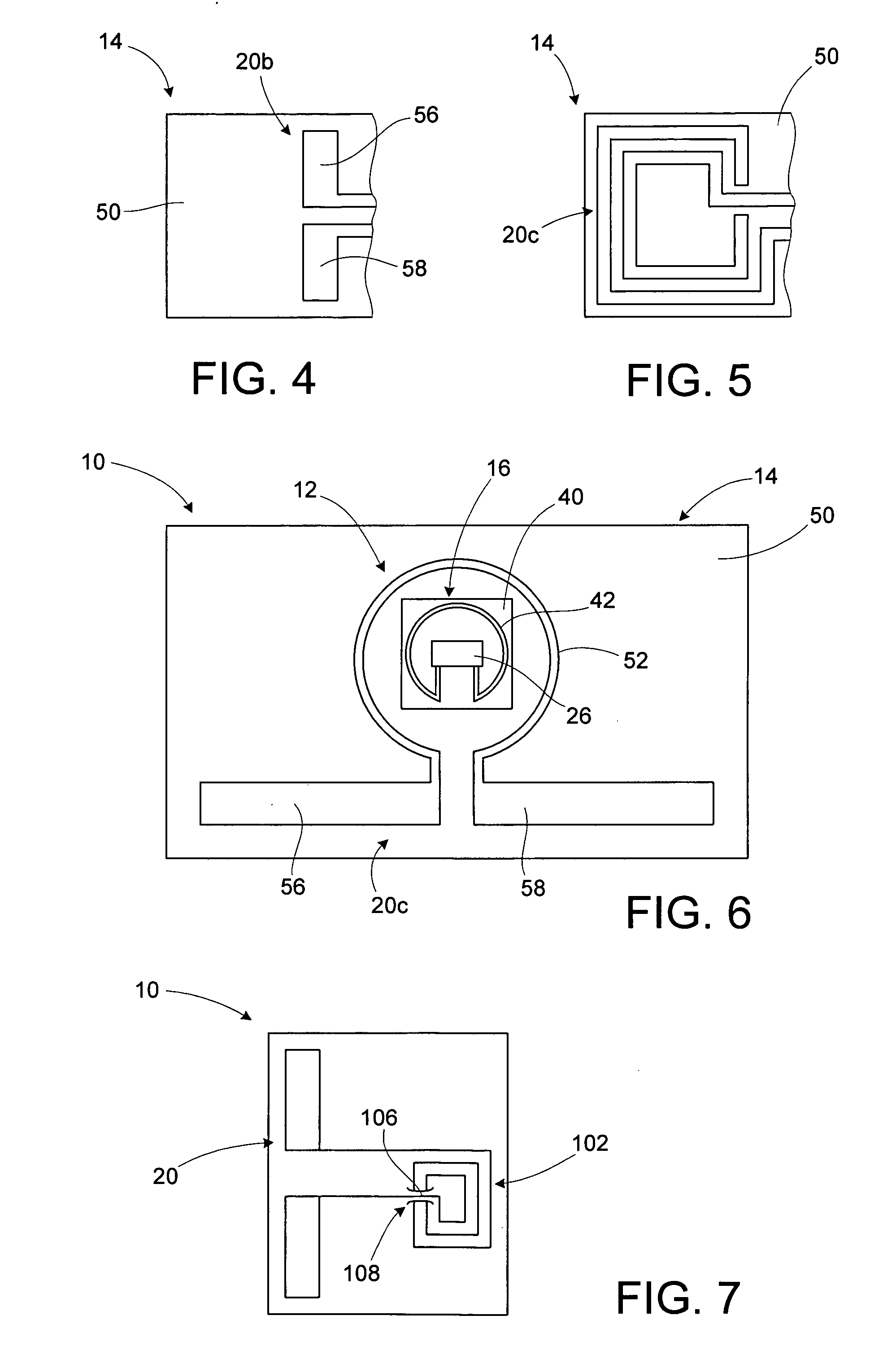
[0028] An RFID device, such as an RFID tag or label, includes a magnetic coupler between an interposer or strap, and an antenna. The interposer or strap includes a transponder chip and an interposer magnetic coupling element that is operatively coupled to the transponder. An antenna portion magnetic coupling element is operatively coupled to the antenna. The magnetic coupling elements together constitute a magnetic coupler that is used to magnetically couple the transponder chip of the interposer to the RFID antenna. A high permeability material may be used to enhance the magnetic coupling between the magnetic coupling elements. The magnetic coupling elements may be conductive loops. The conductive loops may be single-turn conductive loops. Alternatively, one or both of the conductive loops may have multiple turns, thus being conductive coils. The use of multiple-turn conductive loops or coils allows the magnetic coupler to function as a transformer, with the voltage across the ante...


PUM


Abstract

An RFID device, such as an RFID tag or label, includes a magnetic coupler between an interposer or strap, and an antenna. The interposer or strap includes a transponder chip and an interposer magnetic coupling element that is operatively coupled to the transponder. An antenna portion magnetic coupling element is operatively coupled to the antenna. The magnetic coupling element s together constitute a magnetic coupler that is used to magnetically couple the transponder chip of the interposer to the RFID antenna. A high permeability material may be used to enhance the magnetic coupling between the magnetic coupling elements. The magnetic coupling elements single-turn conductive loops or multiple-turn coils. The magnetic coupler may function as a transformer, with the voltage across the antenna transformed to a different voltage across the transponder chip, and vice versa.

Description

BACKGROUND OF THE INVENTION [0001] 1. Field of the Invention [0002] This invention relates to the field of radio frequency identification (RFID) tags and labels. [0003] 2. Description of the Related Art [0004] RFID tags and labels have a combination of antennas and analog and / or digital electronics, which may include for example communications electronics, data memory, and control logic. RFID tags and labels are widely used to associate an object with an identification code. For example, RFID tags are used in conjunction with security-locks in cars, for access control to buildings, and for tracking inventory and parcels. Some examples of RFID tags and labels appear in U.S. Pat. Nos. 6,107,920, 6,206,292, and 6,262,292, all of which this application incorporates by reference. [0005] RFID tags and labels include active tags, which include a power source, and passive tags and labels, which do not. In the case of passive tags, in order to retrieve the information from the chip, a “base ...

Claims


Application Information

Patent Timeline
Patent Type & Authority Applications(United States)
IPC IPC(8): H05K7/06
CPCG06K19/07749H01Q7/00H01Q1/2208G06K19/07756
Inventor FORSTER, IAN J.WEAKLEY, THOMAS CRAIG
Owner AVERY DENNISON CORP
Why Eureka
Try Eureka