Fusing roller and fusing apparatus using the same

a technology of fusing roller and fusing apparatus, which is applied in the field of fusing apparatus, can solve the problems of difficult to achieve an even distribution of temperature over recording media, low thermal efficiency of halogen lamps, and considerable amount of so as to reduce the time required for warming up halogen lamps and quickly increase the temperature of heat sources

Inactive Publication Date: 2006-03-02
S PRINTING SOLUTION CO LTD
View PDF3 Cites 8 Cited by
  • Summary
  • Abstract
  • Description
  • Claims
  • Application Information

AI Technical Summary

Benefits of technology

[0016] The present invention provides a fusing apparatus used with an image forming apparatus, which can reduce the time required for warming a heat source up by quickly increasing the temperature of the heat source to a desired fusing temperature using both resistive heat and induced heat and can adjust the area of a heated portion based on the size of a recording medium.

Problems solved by technology

First, since a halogen lamp has a low thermal efficiency, a considerable amount of time is required for warming the halogen lamp up until the temperature of the halogen lamp reaches a desired fusing temperature.
However, it takes the conventional fusing apparatus a while to compensate for the temperature differences, and thus, it is difficult to achieve an even distribution of temperatures over the recording medium 20.
Finally, since the conventional fusing apparatus applies heat to a predetermined area of a region, regardless of the size of the recording medium 20, elements of the conventional fusing apparatus that do not directly engage with the recording medium 20 may be unnecessarily heated, which results in the deformation or breakdown of the corresponding elements of the conventional fusing apparatus.

Method used


Image

  • Fusing roller and fusing apparatus using the same
  • Fusing roller and fusing apparatus using the same
  • Fusing roller and fusing apparatus using the same

Examples


Embodiment Construction

[0029] Reference will now be made in detail to the embodiments of the present invention, examples of which are illustrated in the accompanying drawings, wherein like reference numerals refer to the like elements throughout. The embodiments are described below to explain the present invention by referring to the figures.

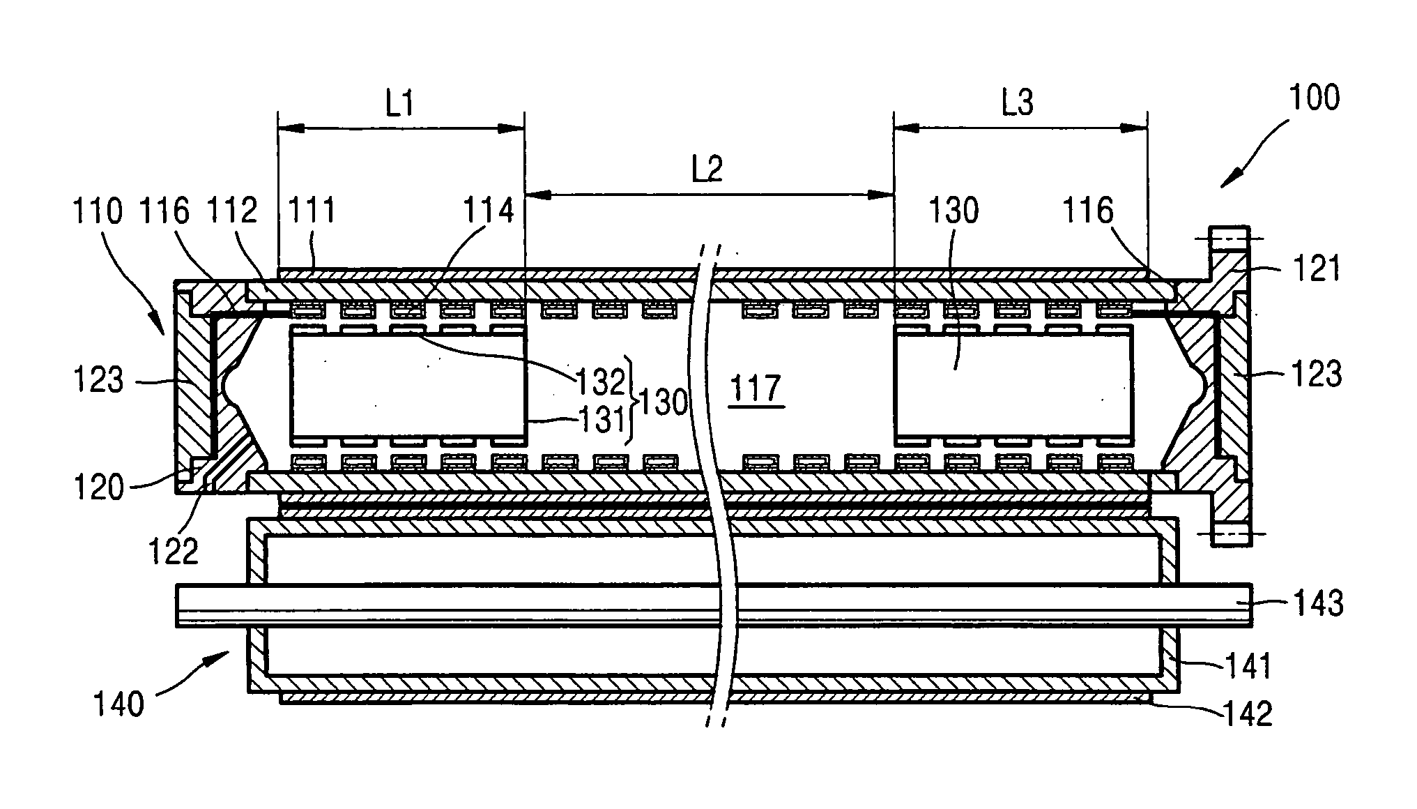
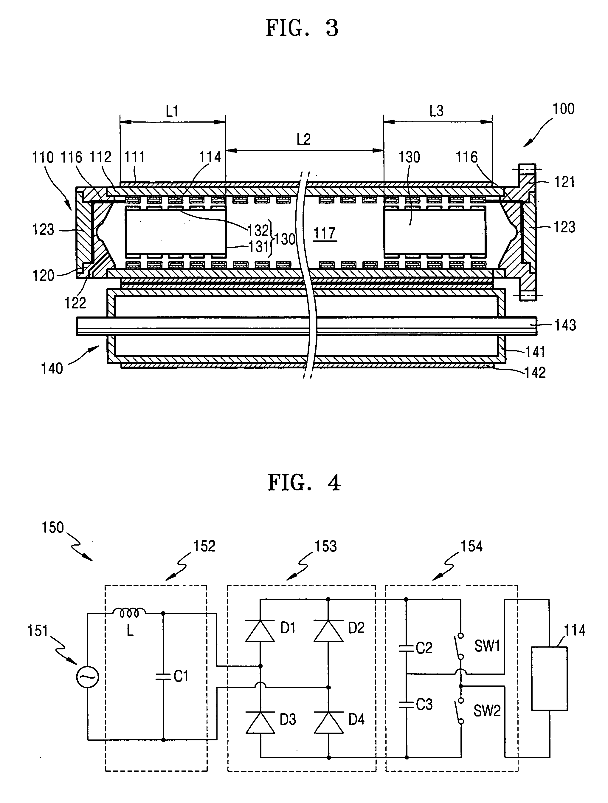
[0030]FIG. 3 is a latitudinal cross-sectional view of a fusing apparatus 100, in which a fusing roller 110 according to an exemplary embodiment of the present invention is installed. FIG. 4 is a circuit diagram of a power supply for the fusing roller 110. FIG. 5 is a diagram illustrating the operation of a compensator of the fusing roller 110. FIG. 6 is a diagram illustrating a heat source of the fusing roller 110.

[0031] Referring to FIGS. 3 and 4, a fusing apparatus 100 includes the fusing roller 110, which generates heat that fuses a toner image (not shown) on to a recording medium (not shown), and a press roller 140, which is installed to contact the fusing rolle...


PUM


Abstract

A fusing roller and a fusing apparatus having the same are provided. The fusing roller includes: an induced coil, which generates an alternating magnetic flux that varies depending on an input alternating current; a heating roller, which is heated by an eddy current that is generated by the alternating magnetic flux; and a compensator, which compensates for the eddy current generated where it is located

Description

CROSS REFERENCE TO RELATED APPLICATION [0001] This application claims the benefit of Korean Patent Application No. 10-2004-0067088, filed on Aug. 25, 2004, in the Korean Intellectual Property Office, the disclosure of which is incorporated herein in its entirety by reference. [0002] 1. Field of the Invention [0003] The present invention relates to a fusing apparatus and, more particularly, to a fusing apparatus having a fusing roller, which can adjust the area of a heated portion based on the size of a recording medium so that heat can only be applied to the recording medium. [0004] 2. Description of the Related Art [0005] In general, electrophotographic image forming apparatuses, such as laser printers or digital copiers, print a unicolored or multicolored image by applying light to a photosensitive medium charged with a predetermined potential to form a latent electrostatic image on the photosensitive medium, enabling a developer to develop the latent electrostatic image with a pr...

Claims


Application Information

Patent Timeline
Patent Type & Authority Applications(United States)
IPC IPC(8): G03G15/20
CPCG03G15/2053G03G15/2025G03G15/2028G03G15/2064H05B6/145
Inventor CHO, DURK-HYUNHAN, SANG-YONGKWON, JOONG-GIKIM, HWAN-GUEMCHAE, YOUNG-MIN
Owner S PRINTING SOLUTION CO LTD
Why Eureka
Try Eureka