Sealed, blind fastener assembly

a technology of fasteners and blinds, which is applied in the direction of fastening means, screws, dowels, etc., can solve the problems of preventing the closure preventing the collapse of the blind fastener located on the blind or inaccessible side of the workpiece, and forming a second flang

Active Publication Date: 2006-03-02
FATIGUE TECH
View PDF37 Cites 38 Cited by
  • Summary
  • Abstract
  • Description
  • Claims
  • Application Information

AI Technical Summary

Benefits of technology

[0010] In one aspect, a sealable blind fastener assembly includes a receiving member having a body with a first end and a second end opposed to the first end, the body having a first outer perimeter and a second outer perimeter smaller than the first out perimeter, the body having an opening extending between the first end and the second end and an engageable strucuture formed therein, at least a portion of the body being collapsible to form a flang...

Problems solved by technology

The tool is operated to pull on the rod, thus causing a portion of the blind fastener located on the blind or inaccessible side of the work piece to collapse and form a second flange.
During the machining of the internal threads, metal shavings and other debris can become trapped between the valleys of the threads and accumulate in the region of the closed end.
One drawback of presently designed blind fasteners is that the integrally formed closed end of the blind fastener prevents the removal of the majority of debris residing in the blind fastener opening after machining.
The failure or inability to remove a substantial amount of debris from the threaded region of the blind fastener can cause stress concentration sites in the thread roots, for example, and lead to premature fracturing of the bolt or the blind fastener while the blind fastener is under an operational load.
In addition, debris can interfere with the proper threading of an accessory bolt or screw that is inserted into the blind fastener.
Debr...

Method used


Image

  • Sealed, blind fastener assembly
  • Sealed, blind fastener assembly
  • Sealed, blind fastener assembly

Examples


Embodiment Construction

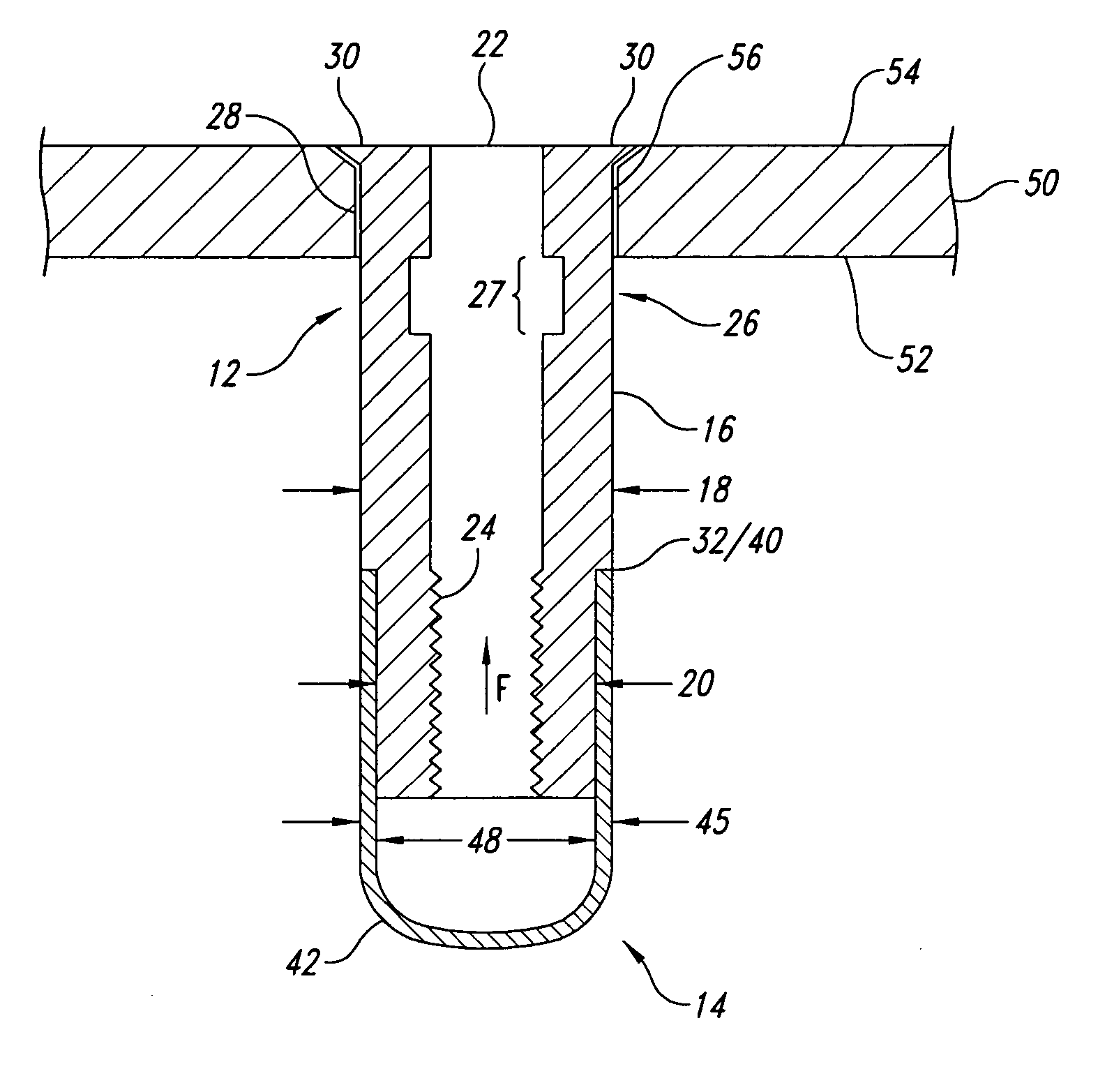
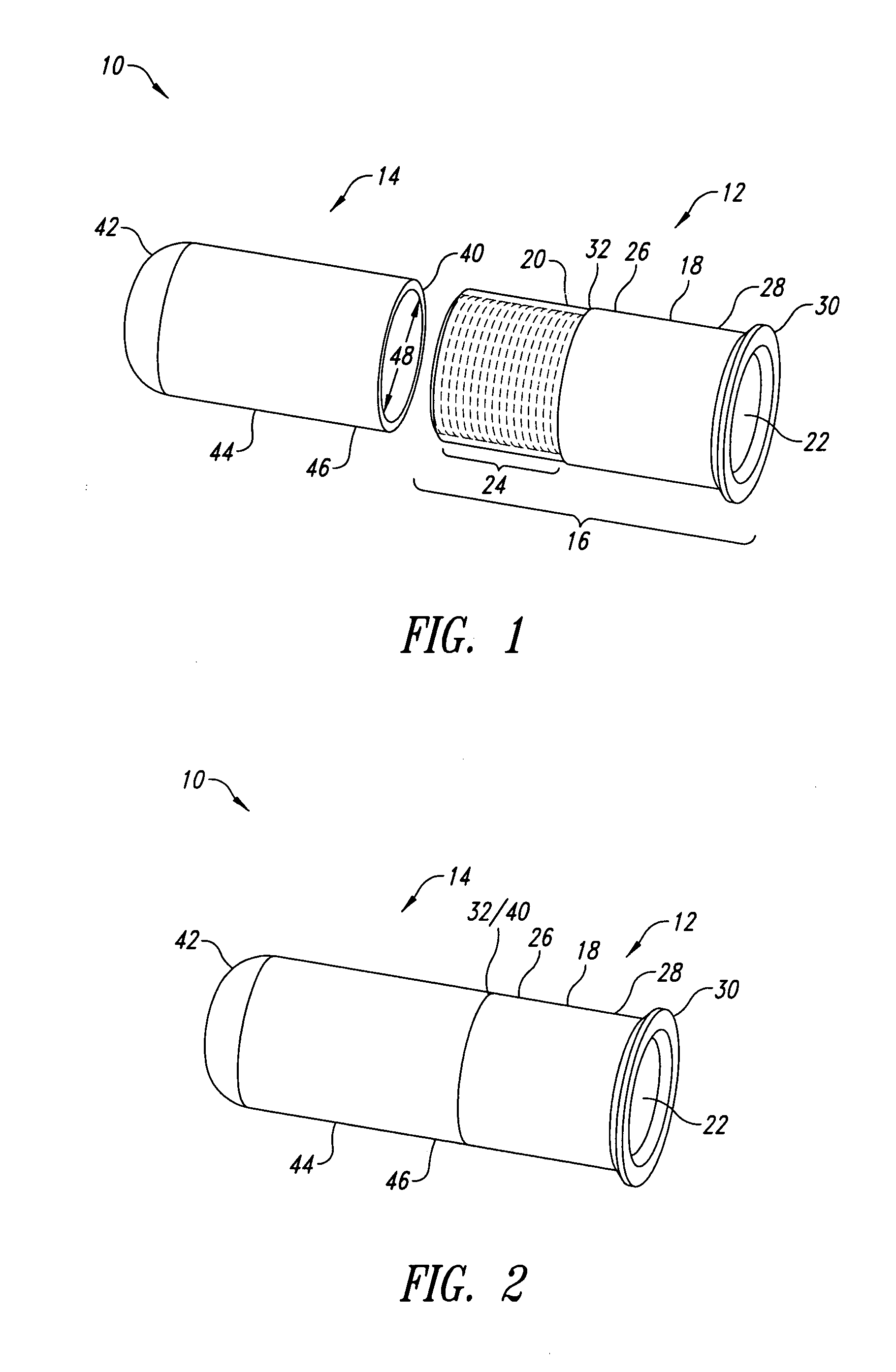
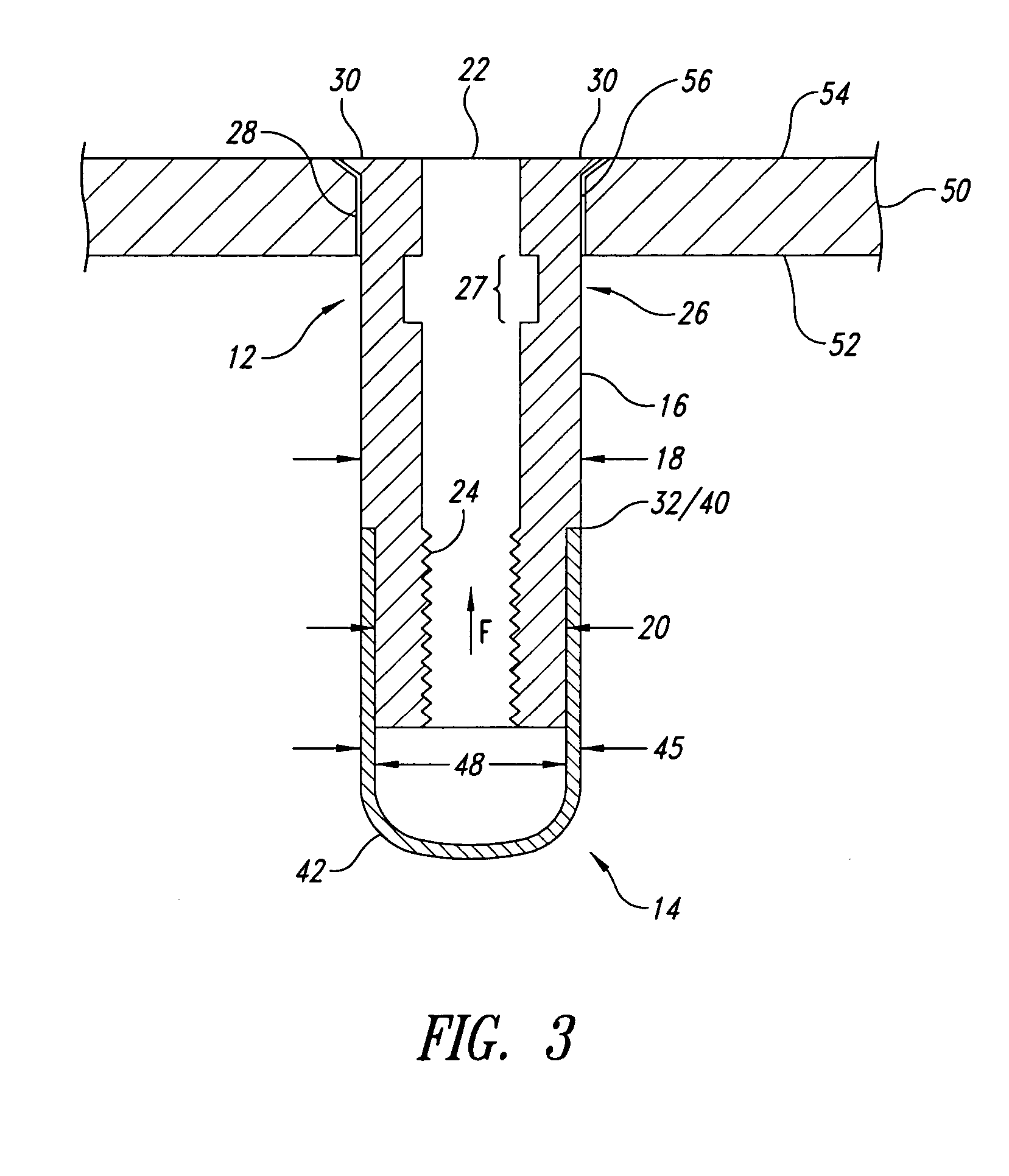
[0018] In the following description, certain specific details are set forth in order to provide a thorough understanding of various embodiments of the invention. However, one skilled in the art will understand that the invention may be practiced without these details. In other instances, well-known structures associated with fastening systems, installation aspects of blind, partially collapsible fastener assemblies, and various types of tooling used to install the blind, partially collapsible fastener assemblies have not been shown or described in detail to avoid unnecessarily obscuring descriptions of the embodiments of the invention.

[0019] Unless the context requires otherwise, throughout the specification and claims which follow, the Word “comprise” and variations thereof, such as, “comprises” and “comprising” are to be construed in an open, inclusive sense, that is as “including, but not limited to.”

[0020] Throughout the disclosure, reference to a blind fastener or blind fasten...


PUM


Abstract

A sealed attachment fastener assembly with a receiving member and a cap that can be inserted into an opening in a work piece and fixed therein from only one side of the work piece. A portion of the fastener assembly on the blind side of the work piece is collapsible into a flange. In addition, another portion of the fastener assembly is contemporaneously radially expandable within the opening of the work piece to at least rotationally secure the fastener assembly with respect to the work piece. The radial expansion will result in a high interference fit of the fastener in the work piece, which may enhance the fatigue of the installation. A cap completes the fastener assembly to substantially prevent fluid from leaking through the fastener assembly opening. The cap can be assembled with the receiving member after the internal threads within the receiving member have been machined.

Description

BACKGROUND OF THE INVENTION [0001] 1. Field of the Invention [0002] This disclosure relates to a sealed, blind, internally threaded fastener assembly that is cold expanded and at least partially collapsible to form a secure fit within a work piece. [0003] 2. Description of the Related Art [0004] The ability to blindly install a fastener into structural work members is well known in the art, particularly in the aerospace industry. As used herein, a blind fastener comprises the nut or receiving portion of a bolt / nut fastener group. Blind fasteners are often used for access panels and other structure where it is difficult or nearly impossible to get a tool onto the back or “blind” side of the panel to hold a nut. Thus the blind fastener, once installed, performs like a nut to receive an attachment bolt so that other structure or accessory devices can be attached to the work piece or access panel, for example. A blind fastener, sometimes referred to as a blind rivet, is typically a cyli...

Claims


Application Information

Patent Timeline
IPC IPC(8): F16B13/04
CPCF16B19/1072F16B5/04
Inventor JOHNSON, TIMOTHY H.REID, LEONARD F.GIBSON, BRUCE F.
Owner FATIGUE TECH
Why Eureka
Try Eureka