
Vane attachment arrangement

Active Publication Date: 2006-03-02
PRATT & WHITNEY CANADA CORP
View PDF20 Cites 13 Cited by
  • Summary
  • Abstract
  • Description
  • Claims
  • Application Information

AI Technical Summary

Benefits of technology

[0004] It is therefore an object of this invention to provide an improve

Problems solved by technology

That is because it is not possible to simultaneously insert two ends of a rigid object into fixed geometry endpoints.
The above assemblies require that several parts be bolted or otherwise fixedly secured together which significantly increase the weight and the cost of the overall vane assembly.

Method used


Image

  • Vane attachment arrangement
  • Vane attachment arrangement
  • Vane attachment arrangement

Examples


Embodiment Construction

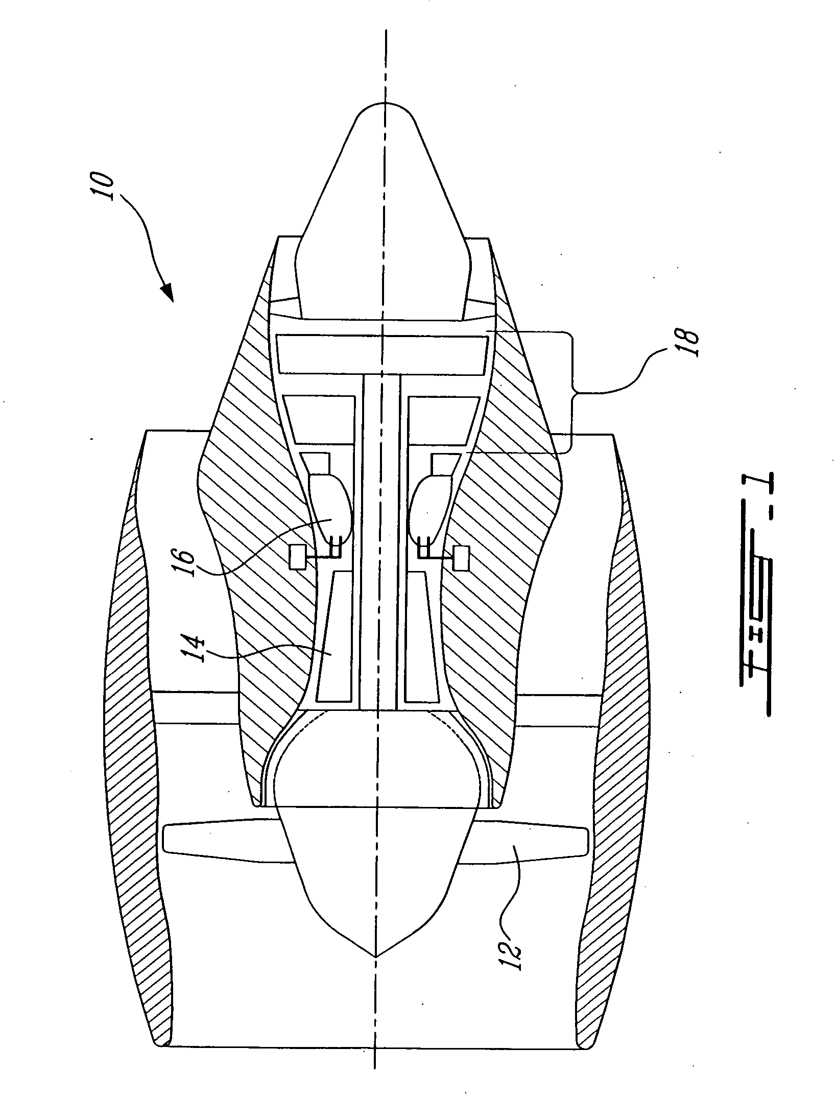
[0014]FIG. 1 illustrates a gas turbine engine 10 of a type preferably provided for use in subsonic flight, generally comprising in serial flow communication a fan 12 through which ambient air is propelled, a multistage compressor 14 for pressurizing the air, a combustor 16 in which the compressed air is mixed with fuel and ignited for generating an annular stream of hot combustion gases, and a turbine section 18 for extracting energy from the combustion gases.

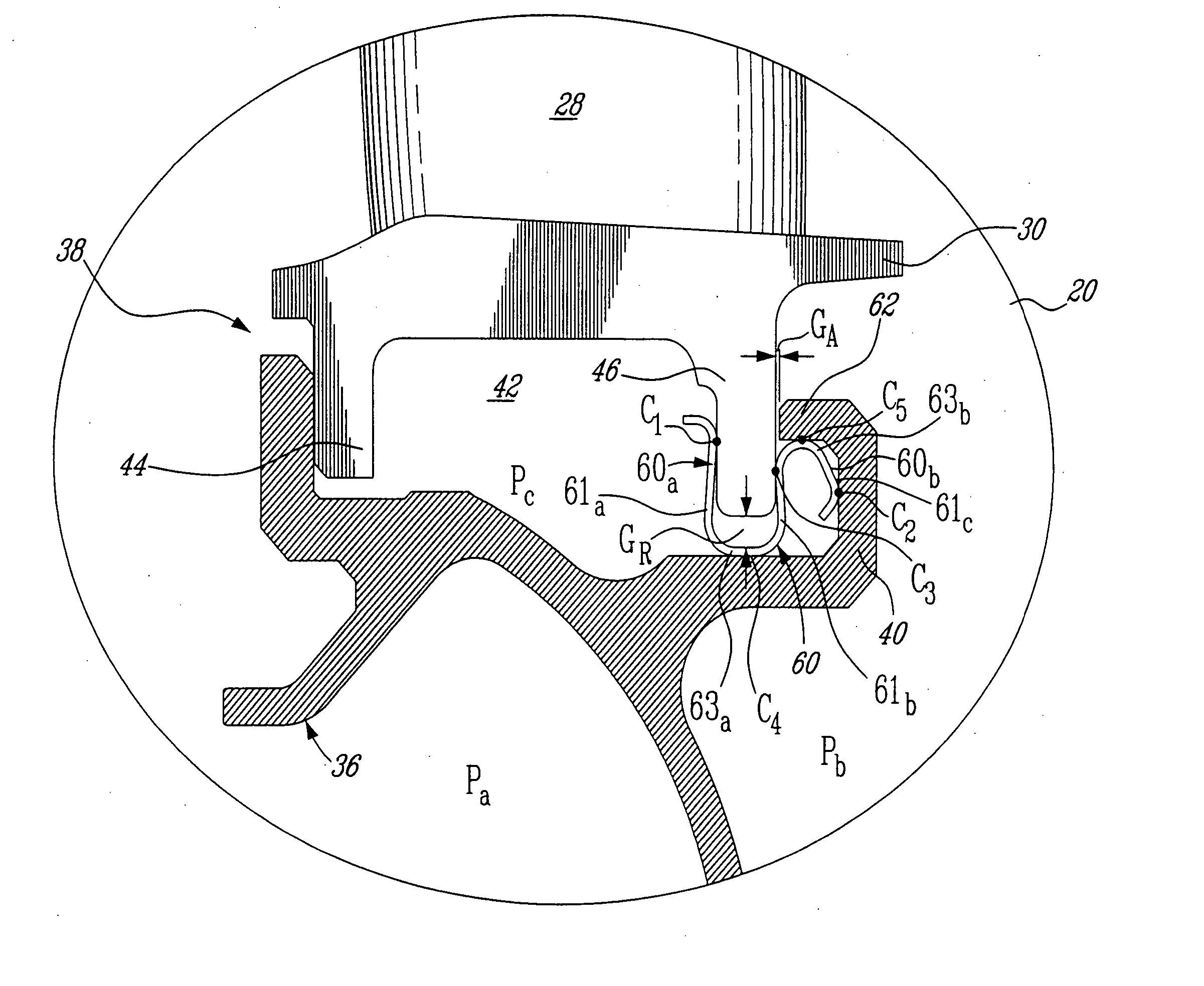
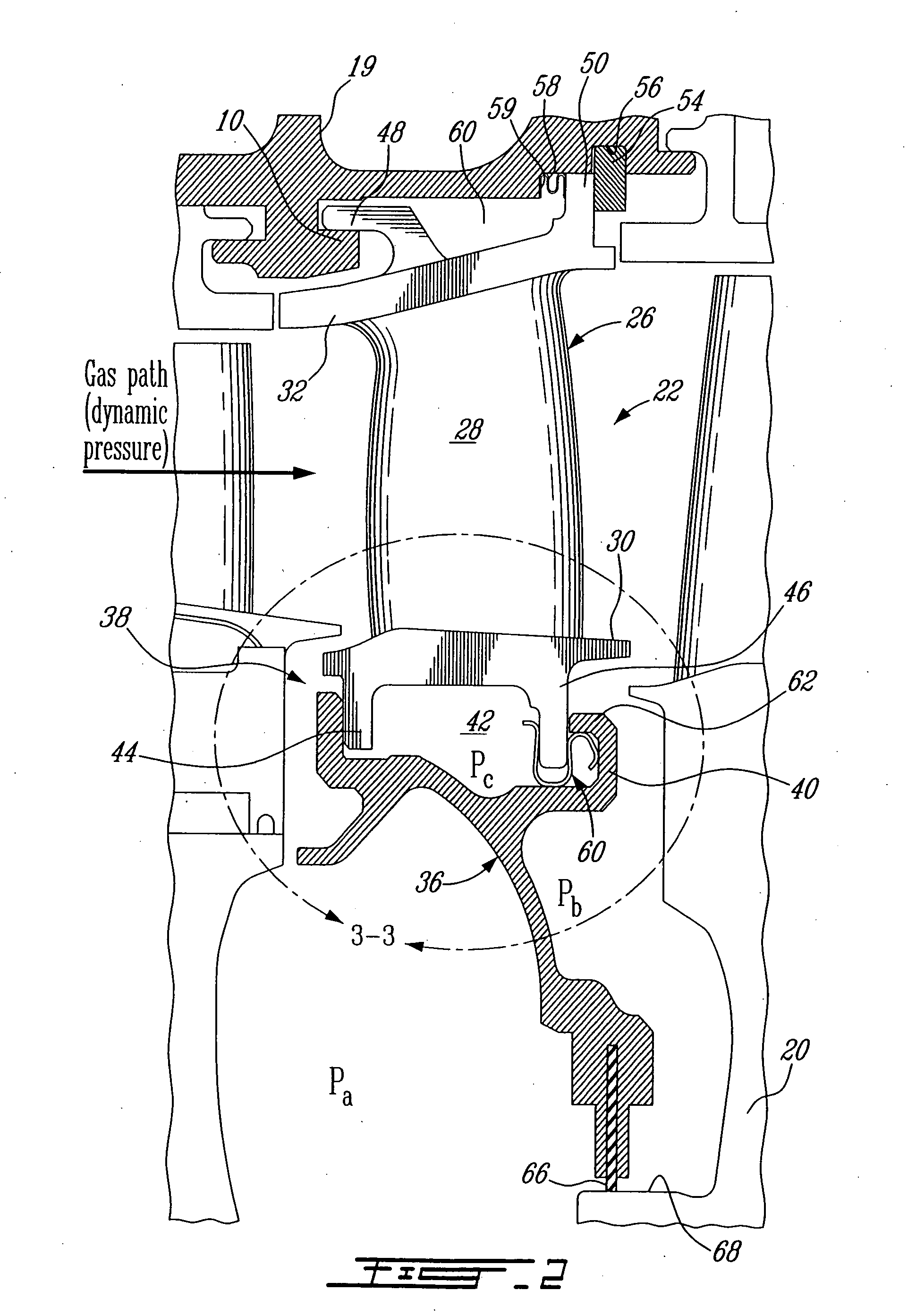
[0015] As shown in FIG. 2, the gas turbine section 18 has one or more stages disposed within an outer casing, such as a turbine support case 19. Each turbine stage commonly comprises a turbine rotor 20 that rotates about a centerline axis of the engine 10 and a stationary vane ring 22 for channelling the combustion gases to the turbine rotor 20. The vane ring 22 is commonly segmented around the circumference thereof with each vane ring segment 26 having a plurality of circumferentially spaced-apart turbine vanes 28 (only one o...


PUM

PropertyMeasurementUnit
Pressureaaaaaaaaaa

Abstract

A simplified vane mounting arrangement by which a vane ring can be pre-assembled to an inner support ring before being installed in an outer casing.

Description

TECHNICAL FIELD [0001] The invention relates generally to gas turbine engines and, more particularly, to an improved vane mounting arrangement. BACKGROUND OF THE ART [0002] In a typical turbine vane mounting arrangement, the vane ring segments are first fixedly mounted to an intermediate inner ring, known as a squirrel cage, or alternatively directly to the outer case by means of a forward hook and an aft hook extending from the outer band of each segment. Then, the inner band of the segments is mounted to a two-piece inner ring. Due to assembly geometry, the inner ring must necessarily be provided in two pieces and assembled, such as by bolting, to the vane ring. That is because it is not possible to simultaneously insert two ends of a rigid object into fixed geometry endpoints. [0003] The above assemblies require that several parts be bolted or otherwise fixedly secured together which significantly increase the weight and the cost of the overall vane assembly. SUMMARY OF THE INVEN...

Claims


Application Information

Patent Timeline
IPC IPC(8): F01D5/30
CPCF01D11/003F01D11/005F01D25/246Y10T29/49323F05D2240/55F05D2240/56F05D2240/57F05D2230/60
Inventor SYNNOTT, REMYGRIVAS, NICOLASJUNEAU, ALANGLASSPOOLE, DAVID
Owner PRATT & WHITNEY CANADA CORP
Learn More