Adaptive power control method for cellular systems

a power control and cellular technology, applied in power management, transmission monitoring, wireless commuication services, etc., can solve the problems of inconvenient system operation, reduced system capacity from an rf perspective, and insufficient load or call traffic over the system in most cases. highly non-uniform distribution of load or call traffi

a power control and cellular technology, applied in power management, transmission monitoring, wireless commuication services, etc., can solve the problems of inconvenient system operation, reduced system capacity from an rf perspective, and insufficient load or call traffic over the system in most cases. highly non-uniform distribution of load or call traffi

US20060046735A1Active Publication Date: 2006-03-02GOOGLE TECH HLDG LLC

Image

  • Adaptive power control method for cellular systems
  • Adaptive power control method for cellular systems
  • Adaptive power control method for cellular systems

Examples


Embodiment Construction

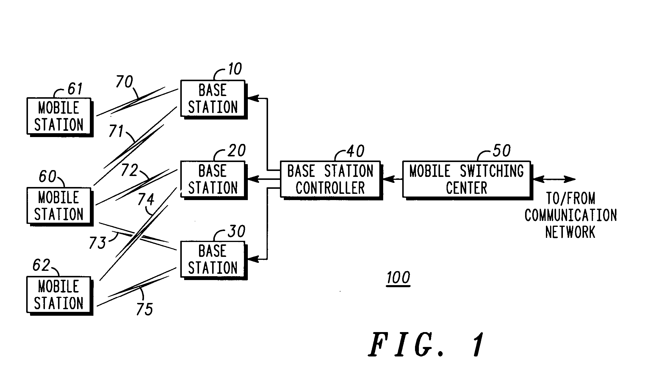
[0010]FIG. 1 is a block diagram depicting a cellular communication system 100. Cellular communication system 100 includes mobile switching center (MSC) 50 coupled to base station controller (BSC) 40. Base station controller 40 is coupled to base stations (BTS) 10, 20 and 30. Base stations 10-30 are coupled to mobile stations 60, 61, and 62.

[0011] Each mobile station 60-62 is coupled to at least one of the base stations 10-30. Mobile station 60 is coupled to each base station 10-30 via mobile links 71, 72 and 73 respectively. Each of these mobile links may also be referred to as “call legs” or “soft handoff legs”. Mobile station 60 is coupled to each of the base stations 10-30 since it is in “soft-handoff” (SHO) with these base stations (and thus has multiple soft-handoff legs). The base stations are constantly transmitting the same data for diversity benefits. Within a call, base stations or soft-handoff legs may be dropped and others may be added.

[0012] Mobile station 61 is couple...


PUM


Abstract

A method for adaptive power control in a mobile communication system (100) determines (120) whether an RF loading factor (110) is greater than a threshold value. If the RF loading factor is above the threshold value, the method reduces call quality (140). Next, a determination is made whether the RF loading factor is below a second threshold value (150). If the RF loading factor is below the second threshold value, the call quality of the mobile communication system is increased (160).

Description

BACKGROUND OF THE INVENTION [0001] The present invention pertains to cellular communication systems and more particularly to a method for conserving power and system capacity during peak communication system loading. [0002] In current cellular systems, target Frame Erasure Rate (FER) settings and power control parameters are set statically and are independent of the actual load on the system which is dynamic. The FER measures dropped frames or quality of a link in a communication system. [0003] In a CDMA system, there is a strong relationship between system capacity, RF power, interference, and call quality. As call quality is increased, the power consumed by the system tends to increase. This situation consumes available cell power which is limited, and increases system interference which in turn reduces system capacity from an RF perspective. This is a particularly important aspect of efficient CDMA systems. [0004] Call quality in this context includes voice quality which can be m...

Claims


Application Information

Patent Timeline
02 Mar 2006
Publication
US20060046735A1
IPC
H04Q7/20; H04W24/00; H04W24/02; H04W52/34
CPC
H04W24/00; H04W52/343; H04W24/02; H04W28/04; H04W28/18; H04W52/265
Inventors
GROSS, JONATHAN H.; HARRIS, JOHN M.