
Axi-centrifugal compressor

a compressor and centrifugal technology, applied in the direction of machines/engines, mechanical equipment, liquid fuel engines, etc., can solve the problems of increasing the volume, weight and cost of the engine, reducing the value and competitive position of the engine, and increasing the diameter of the impeller, so as to achieve low cost, light weight, and high pressure rise

Inactive Publication Date: 2017-09-28
HONEYWELL INT INC
View PDF5 Cites 11 Cited by
  • Summary
  • Abstract
  • Description
  • Claims
  • Application Information

AI Technical Summary

Benefits of technology

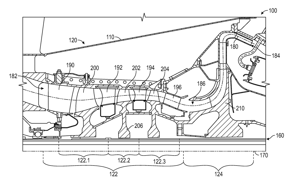
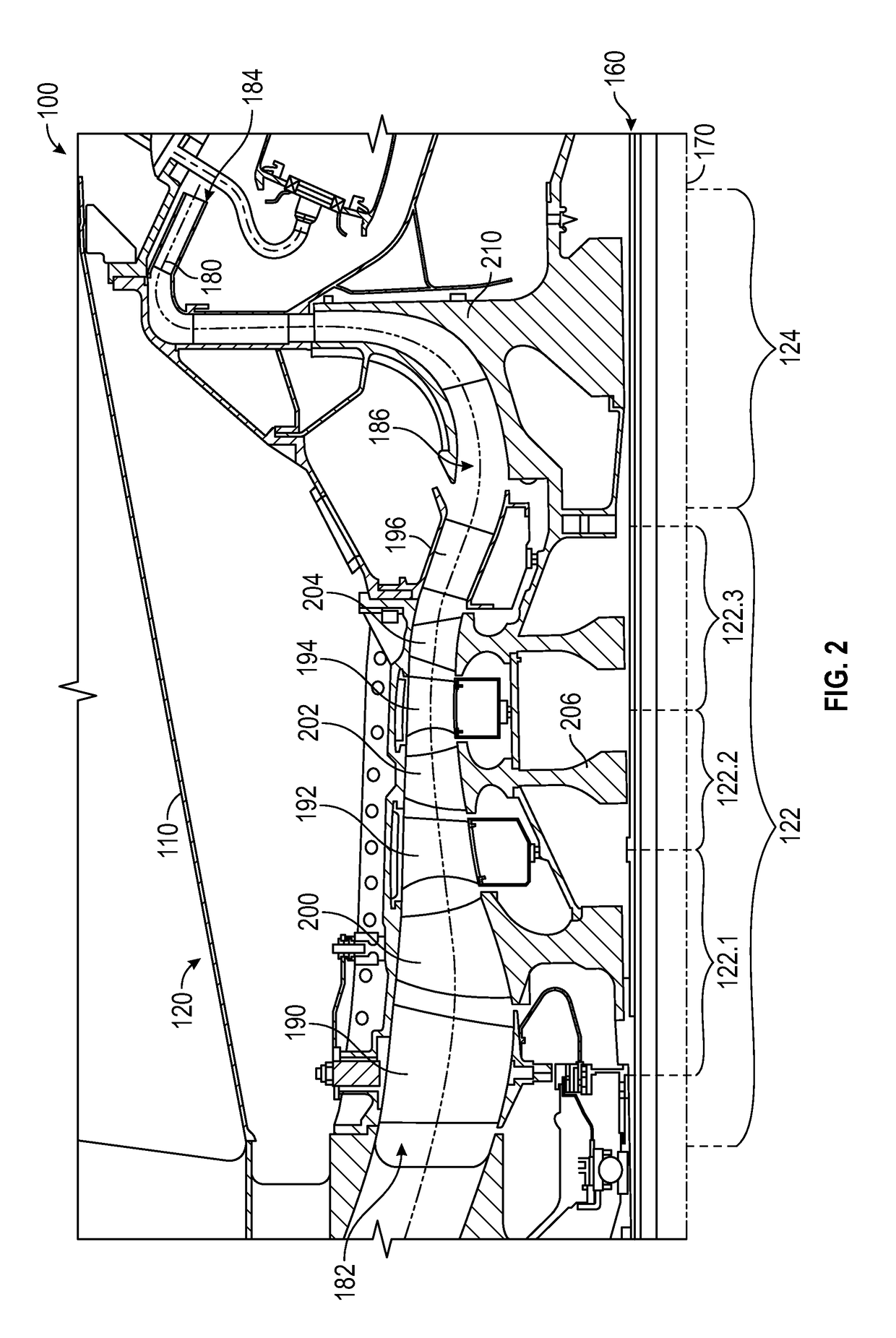
The present invention is a compressor design that provides a uniform distribution of pressure ratio across the compressor. This design increases the pressure rise on the axial portion of the compressor, reducing the size and weight of the centrifugal stage and minimizing the number of stages needed. This results in a smaller, lighter, and more cost-effective compressor compared to conventional designs. Additionally, the design reduces the likelihood of boundary layer separations and improves compressor operability.

Problems solved by technology

However, this is typically done by increasing the number of compressor stages, which increases the volume, weight, and cost of the engine; all of which reduce the value and competitive position of the engine.
The centrifugal compressor provides a second mechanism to increase overall pressure rise but often results in an increase of the diameter of the impeller in the centrifugal stage, resulting in increased weight and engine size.
Unfortunately, this may require a relatively large and heavy centrifugal compressor section to achieve the overall pressure rise across the compressor.

Method used


Image

  • Axi-centrifugal compressor
  • Axi-centrifugal compressor
  • Axi-centrifugal compressor

Examples


Embodiment Construction

[0013]The following detailed description is merely exemplary in nature and is not intended to limit the invention or the application and uses of the invention. As used herein, the word “exemplary” means “serving as an example, instance, or illustration.” Thus, any embodiment described herein as “exemplary” is not necessarily to be construed as preferred or advantageous over other embodiments. All of the embodiments described herein are exemplary embodiments provided to enable persons skilled in the art to make or use the invention and not to limit the scope of the invention which is defined by the claims. Furthermore, there is no intention to be bound by any expressed or implied theory presented in the preceding technical field, background, brief summary, or the following detailed description.

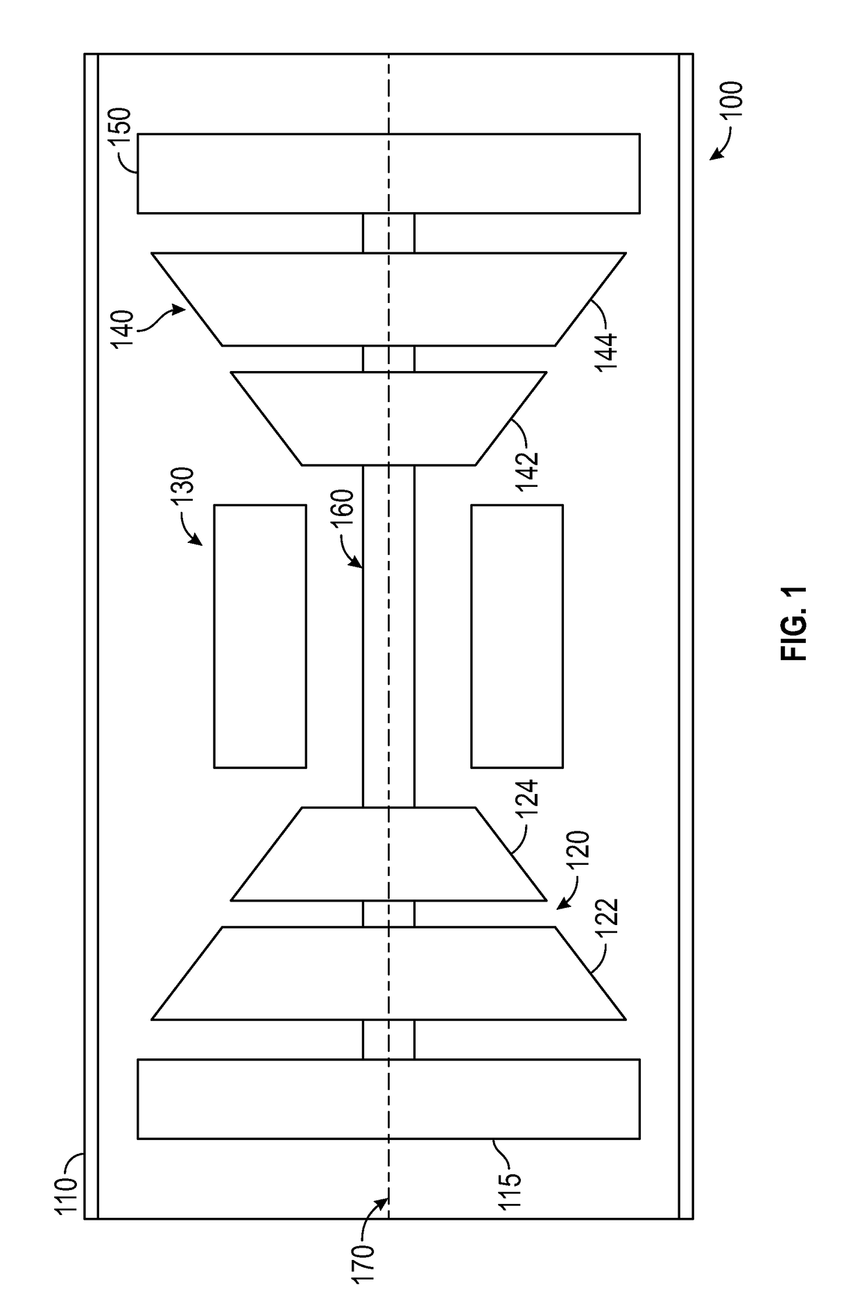
[0014]Broadly, exemplary embodiments discussed herein include an axi-centrifugal compressor configuration having an proportioned pressure ratio distribution across the compressor. A relatively ...


PUM


Abstract

Methods and apparatus are provided for an axi-centrifugal compressor in a gas turbine engine for a business aviation or rotorcraft propulsion unit. The compressor includes an axial compressor section operable to affect a first pressure ratio along the flow path between a compressor inlet and a first section exit, and a centrifugal compressor section operable to affect a second pressure ratio along the flow path between a second section inlet and the compressor exit. The pressure rise across the axial and centrifugal compressor section is configured to have a tuning factor is in a range between 2.8 and 4.5 and a loading factor in a range between 0.6 and 0.8.

Description

TECHNICAL FIELD[0001]The present disclosure generally relates to a gas turbine propulsion system, and more particularly relates to an axi-centrifugal compressor in which a proportioned distribution of the pressure rise across the axial and centrifugal compressor sections is achieved.BACKGROUND[0002]Gas turbine propulsion systems for aircraft must deliver high performance in a compact, lightweight configuration. This is particularly important in smaller jet propulsion systems typically used in regional and business aviation applications as well as in other turbofan, turboshaft, turboprop and rotorcraft applications. A well-known way to improve engine efficiency is to increase the overall pressure rise of the compressor. However, this is typically done by increasing the number of compressor stages, which increases the volume, weight, and cost of the engine; all of which reduce the value and competitive position of the engine. Larger commercial transport engines typically utilize “all-...

Claims


Application Information

Patent Timeline
IPC IPC(8): F02C3/08F04D29/54F04D29/32F04D17/02F04D29/28
CPCF02C3/08F04D17/025F04D29/286F05D2240/35F04D29/542F05D2220/32F04D29/321F04D19/02F05D2220/3216F04D19/028
Inventor NOLCHEFF, NICKREPP, JOHNREYNOLDS, BRUCE DAVIDHANSON, DAVID RICHARD
Owner HONEYWELL INT INC
Learn More