
Vehicular control system for regenerative braking

Inactive Publication Date: 2006-03-02
DEERE & CO
View PDF10 Cites 68 Cited by
  • Summary
  • Abstract
  • Description
  • Claims
  • Application Information

AI Technical Summary

Benefits of technology

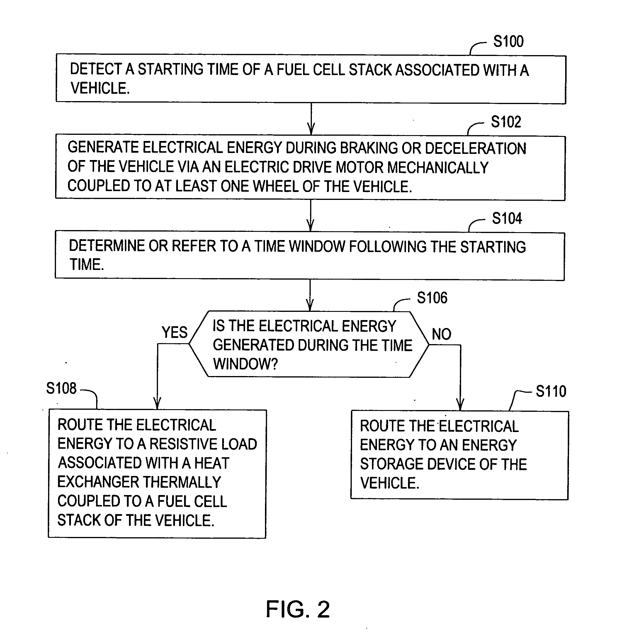
[0003] In accordance with one aspect of the invention, a system and method for controlling a vehicle for regenerative braking facilitates decreasing the warm-up time of the fuel cell stack from start-up (e.g., cold start-up) to full electrical power generation capacity. A controller detects a starting time of a fuel cell stack associated with a vehicle. A controller refers to or determines a time window following the starting time, where the time window is based on at least one of the following factors: (1) lapse of a minimum threshold period of time from the starting time, (2) an ambient temperature around the vehicle or fuel cell, (3) temperature of the fuel cell stack reaches a desired operational temperature or range, and (4) whether the start of the fuel cell occurred as a cold start or a warm start. A drive motor generates electrical energy during braking or deceleration of the vehicle, where the drive motor is mechanically coupled to at least one wheel of the vehicle. A switching unit routes the electrical energy to a resistive load associated with a heat exchanger thermally coupled to a fuel cell stack of the vehicle if the electrical energy is generated during the time window.

Problems solved by technology

In the prior art, locomotives or other diesel-electric hybrid vehicles may dissipate such generated electrical energy as wasted thermal energy in resistors.
For fuel-cell powered vehicles, from time to time the electrical energy generated by regenerative braking may exceed the available storage capacity of the vehicular batteries; adding additional batteries may appreciably increase the price and weight of the vehicle.

Method used


Image

  • Vehicular control system for regenerative braking
  • Vehicular control system for regenerative braking
  • Vehicular control system for regenerative braking

Examples


Embodiment Construction

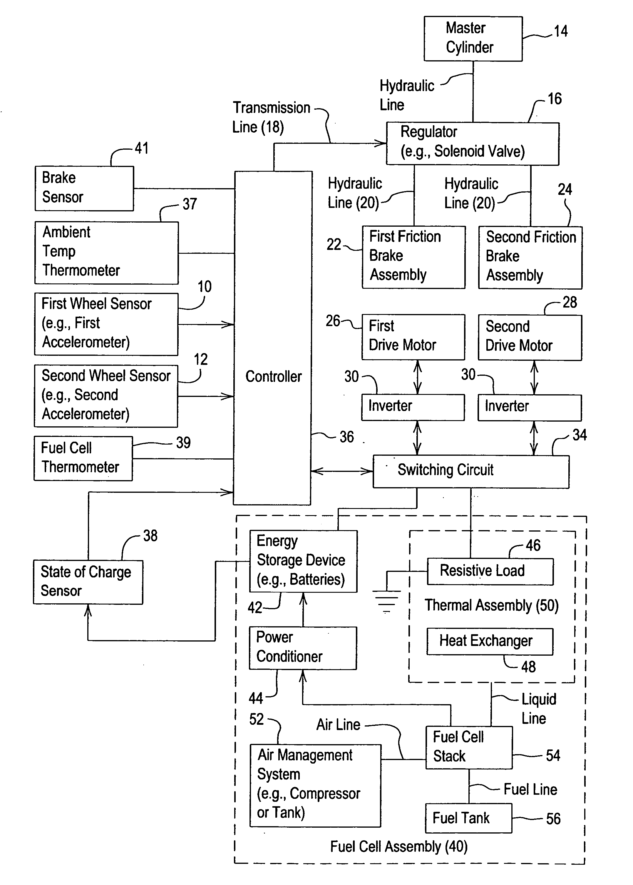
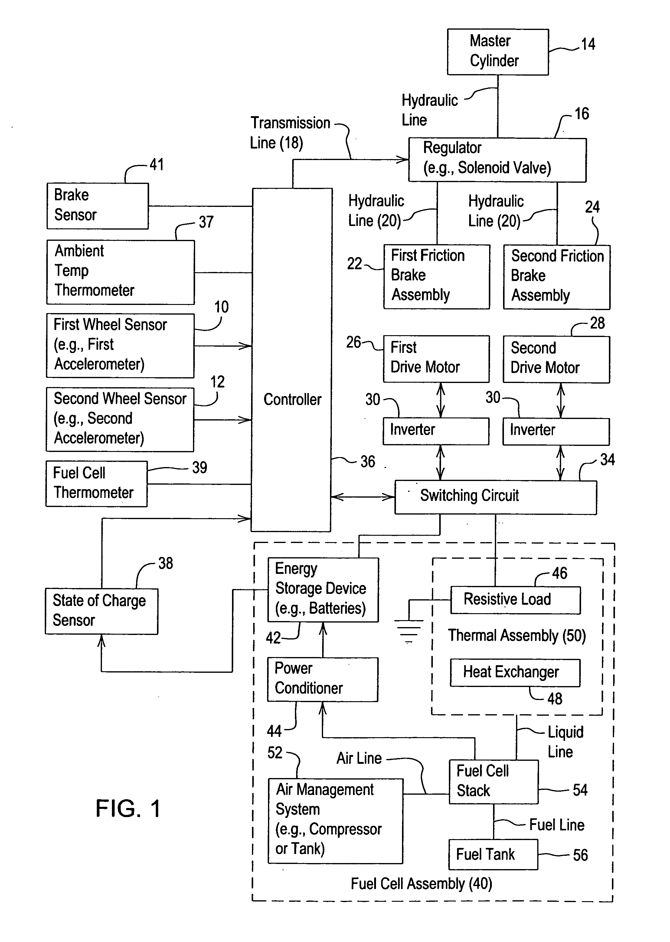
[0012] In FIG. 1 in accordance with one embodiment, a system for controlling a vehicle or managing electrical energy associated with a vehicle comprises a first drive motor 26 and a second drive motor 28. The first drive motor 26, the second drive motor 28, or both are coupled to wheels of the vehicle to propel the vehicle in a propulsion mode or to decelerate the vehicle in a regenerative braking mode. Regenerative braking refers to using the first drive motor 26, the second drive motor 28, or both to oppose the motion of the vehicle. During the regenerative braking mode, one or more of the drive motors (26, 28) convert the kinetic energy of the moving vehicle into electrical energy; the fuel cell assembly 40 may provide a load or energy storage device 42 to accept electrical energy generated by one or more drive motors (26, 28).

[0013] In contrast, during the propulsion mode, the energy storage device 42, the fuel cell stack 54, or the fuel cell assembly 40 provides electrical pow...


PUM


Abstract

A system and method for controlling a vehicle for regenerative braking facilitates decreasing the warm-up time of the fuel cell stack from start-up to full electrical power generation capacity. A controller detects a starting time of a fuel cell stack associated with a vehicle. A drive motor generates electrical energy during braking or deceleration of the vehicle, where the drive motor is mechanically coupled to at least one wheel of the vehicle. A controller refers to or determines a time window following the starting time. The switching unit routes the electrical energy to a resistive load associated with a heat exchanger thermally coupled to a fuel cell stack of the vehicle if the electrical energy is generated during the time window.

Description

FIELD OF THE INVENTION [0001] This invention relates to a vehicular control system for regenerative braking. BACKGROUND OF THE INVENTION [0002] A regenerative braking unit may comprise a traction motor that is used to slow or to stop a vehicle. For example, the regenerative braking unit may act as a generator that converts mechanical energy of wheel rotation into electrical energy. In the prior art, locomotives or other diesel-electric hybrid vehicles may dissipate such generated electrical energy as wasted thermal energy in resistors. For fuel-cell powered vehicles, from time to time the electrical energy generated by regenerative braking may exceed the available storage capacity of the vehicular batteries; adding additional batteries may appreciably increase the price and weight of the vehicle. Therefore, there is need to enhance the energy management of electrically-driven fuel cell vehicles that are equipped with regenerative braking. SUMMARY OF THE INVENTION [0003] In accordanc...

Claims


Application Information

Patent Timeline
IPC IPC(8): B60K41/02B60W10/08B60K6/20B60W10/18B60W10/26B60W10/28B60W30/18H01M8/04
CPCB60L7/26Y02T10/648B60W10/08B60W10/18B60W10/26B60W10/28B60W30/18127H01M8/04029H01M8/04037H01M8/04268H01M8/0432H01M8/04365H01M8/04955H01M2250/20Y02T90/34Y02E60/50Y02T90/32B60L1/003B60L3/0061B60L3/0076B60L7/06B60L7/14B60L7/22B60L11/005B60L11/1803B60L11/1861B60L11/1885B60L11/1887B60L11/1892B60L11/1894B60L2210/30B60L2210/40B60L2220/42B60L2240/36B60L2240/461B60L2240/545B60L2240/662B60L2250/26B60L2200/26Y10T477/24Y02T10/7044Y02T10/705Y02T10/7241Y02T10/7022Y02T90/16Y02T10/7291B60L2240/80B60L50/40B60L50/51B60L58/31B60L58/40B60L58/33B60L58/34B60L58/15Y02T10/64Y02T10/70Y02T10/72Y02T90/40B60K6/00H01M8/04007
Inventor THACHER, RUSSELL JAMESMUSSER, JAMES WILLIAM
Owner DEERE & CO
Learn More