
Wireless tag system, wireless tag access control device, wireless tag access control method, wireless tag access control program and wireless tag

Inactive Publication Date: 2006-03-02
FUJITSU LTD
View PDF17 Cites 25 Cited by
  • Summary
  • Abstract
  • Description
  • Claims
  • Application Information

AI Technical Summary

Benefits of technology

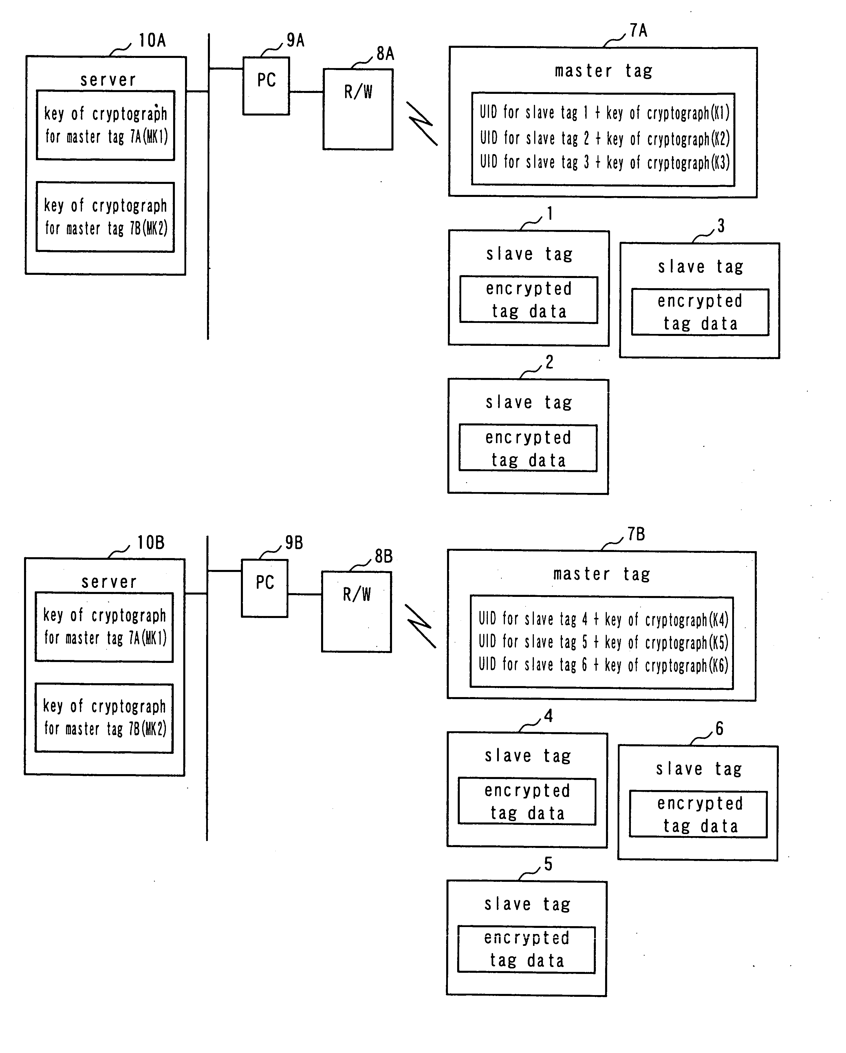
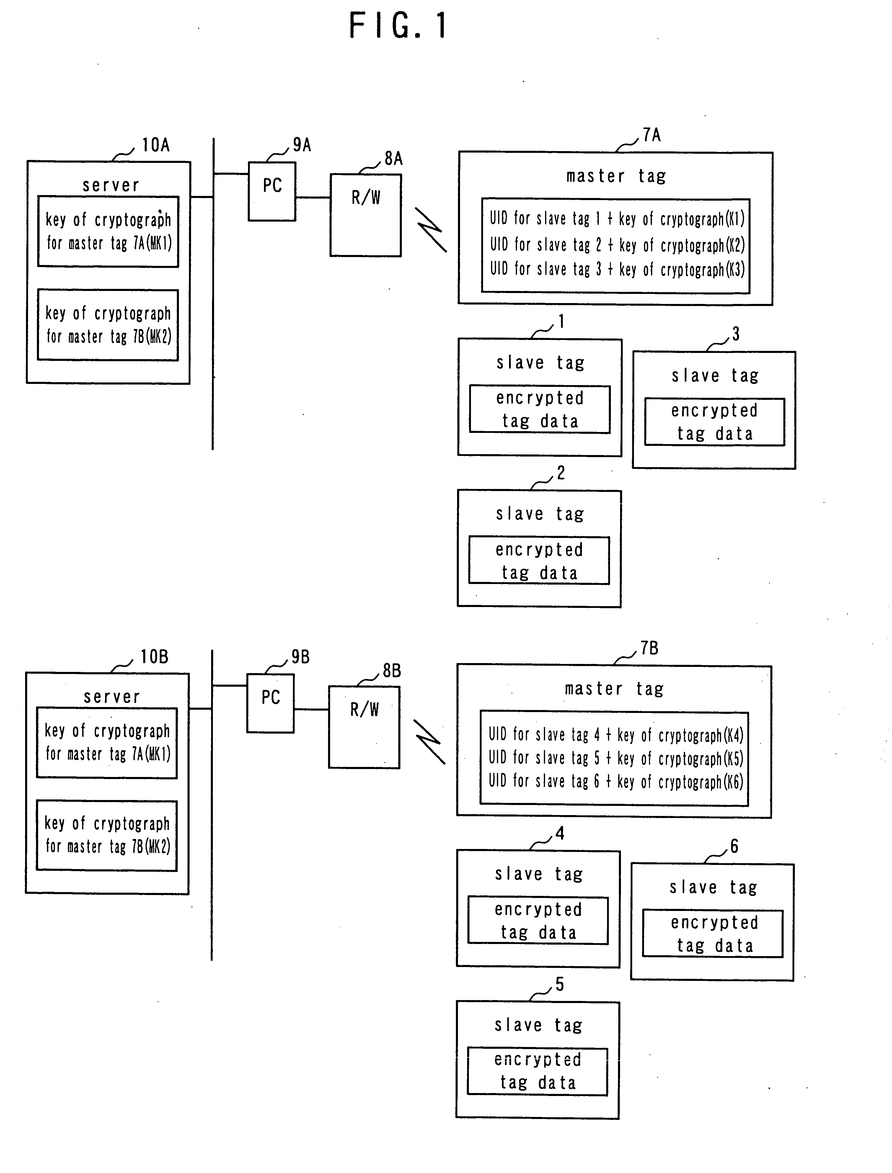
[0018] In view of the above identified problem hitherto known, it is therefore an object of the present invention to provide a wireless tag system with which it is easy to keep and manage keys of cryptograph with an enhanced level of security along with a wireless tag access control device, a wireless tag access control method, a wireless tag access control program and a wireless tag that can be used for such a wireless tag system.
[0035] Thus, the present invention provides an advantage of easiness of keeping and managing keys of cryptograph with an enhanced level of security. Additionally, the present invention provides another advantage that it is not necessary to store a huge number of UIDs of slave tags collectively in a read / write device and the anti-collision processing operation can be carried out fast.

Problems solved by technology

However, since a single key of cryptograph is used for all the tags with the above-described arrangement, it is no longer appropriate to access any of the tags by means of the key of cryptograph for tags once the key is leaked, or stolen.
Therefore, such a system is unsatisfactory from the viewpoint of security.
However, when the wireless tag system is applied to the management of a commodity distribution system in place of a bar code system, the number of tags may be enormous and tens of millions of tags may have to be used.
If there are a large number of host devices such as servers, there arises a problem that each of the host devices has to keep and manage the keys of cryptograph of the respective tags with difficulty.

Method used


Image

  • Wireless tag system, wireless tag access control device, wireless tag access control method, wireless tag access control program and wireless tag
  • Wireless tag system, wireless tag access control device, wireless tag access control method, wireless tag access control program and wireless tag
  • Wireless tag system, wireless tag access control device, wireless tag access control method, wireless tag access control program and wireless tag

Examples


first embodiment

[0050]FIG. 1 is a schematic block diagram of the first embodiment of wireless tag system according to the invention, illustrating the overall configuration thereof. Referring to FIG. 1, the wireless tag system comprises a plurality of slave tags that are divided into two groups of slave tags 1 through 3 and slave tags 4 through 6, master tags 7A, 7B provided for the respective groups of slave tags, read / write devices (R / W) 8A, 8B adapted to access the respective groups of the master tag 7A and the slave tags 1 through 3 and the master tag 7B and the slave tags 4 through 6, PCs 9A, 9B that control the respective read / write devices 8A, 8B and servers 10A, 10B that are connected to the respective PCs 9A, 9B so as to hold and manage the keys of cryptograph for the master tags 7A, 7B and give them to the PCs 9A, 9B whenever necessary, the servers 10A, 10B being the host devices of the respective PCs 9A, 9B.

[0051] The plurality of slave tags 1 through 6 have respective own UIDs and store...

second embodiment

[0067] In the second embodiment, the master tags are made to store the encryption system (e.g., DES / RSA system) of the keys of cryptograph for slave tags along with the keys of cryptograph for slave tags in order to further enhance the security level. When decrypting or encrypting slave tag data, the PC decrypts or encrypts, whichever appropriate, the slave tag data, using the encryption system along with the keys of cryptograph.

[0068]FIG. 6 is a schematic illustration of the contents of the memory of a master tag of the second embodiment. Referring to FIG. 6, the master tag 7 stores encryption system identifiers such as encryption system identifiers D1 through D3 for identifying the DES / RSA system along with the keys of cryptograph for slave tags K1 through K3 so as to correspond to the UIDs of the respective slave tags. Preferably, the encryption system identifiers D1 through D3 for slave tags are also encrypted by means of a key of cryptograph for a master tag as described above...

third embodiment

[0069]FIGS. 7A and 7B are schematic illustrations of the contents of the memory of a master tag and those of the memory of a slave tag of the third embodiment. Referring to FIGS. 7A and 7B, the slave tag data (slave tag information) is divided into a plurality of blocks (1) through (3) and the key of cryptograph for the slave tag is encrypted for each of the blocks by means of a predefined key of cryptograph for the data block and stored in the memory section of the slave tag in order t further enhance the security level. On the other hand, the master tag stores the encryption system identifiers for the data blocks (DB1 through DB3) and the keys of cryptograph for the data blocks (KB1 through KB3) so as to correspond to the slave tag.

[0070] With the above described arrangement, the PC 9 decrypts the encryption system identifiers for the data blocks acquired from the master tag and the keys of cryptograph for the data blocks by means of the key of cryptograph for the master tag acqu...


PUM


Abstract

A wireless tag system and a wireless tag access control device make it easy to keep and manage keys of cryptograph with an enhanced level of security. The wireless tag system comprises a plurality of wireless slave tags 1 through 3 which store information encrypted by means of a first key of cryptograph, a wireless master tag 7A which store the first keys of cryptograph of the slave tags belonging thereto encrypted by means of the second key of cryptograph and a wireless tag access control device which accesses the master tag 7A and decrypting the first keys of cryptograph acquired from the master tag 7A by means of the second key of cryptograph and then the tag data acquired from the slave tags 1 through 3 by means of the decrypted first keys of cryptograph.

Description

BACKGROUND OF THE INVENTION [0001] 1. Field of the Invention [0002] This invention relates to a wireless tag system adapted to communications between a plurality of wireless tags (to be also referred to as IC tags hereinafter) and a read / write device and also to a wireless tag access control device, a wireless tag access control method, a wireless tag access control program and a tag that can be used for such a wireless tag system. [0003] 2. Description of Related Art [0004] As a result of the rapid development of IC technologies in recent years, wireless tag systems using ICs have become very popular and are currently spreading very fast (see, inter alia, Patent Document 1: Japanese Patent Application Laid-Open Publication No. 2003-196360). [0005] With such a wireless tag system, a plurality of wireless tags are attached to respective objects that have to be held under control so that any of the tags can be accessed by way of a read / write device in order to read information from an...

Claims


Application Information

Patent Timeline
IPC IPC(8): H04L9/00G06F1/00G06F21/62G06K17/00G07F7/10H04B5/02H04L9/08H04L9/32
CPCG06Q20/341G07F7/1008G06Q20/35785G06Q20/2295G06K17/00
Inventor HASHIMOTO, SHIGERUHAENO, TADASHI
Owner FUJITSU LTD
Learn More