Oil discharge structure of baffle plate

Active Publication Date: 2006-03-09
JATCO LTD
View PDF28 Cites 61 Cited by
  • Summary
  • Abstract
  • Description
  • Claims
  • Application Information

AI Technical Summary

Benefits of technology

[0011] According to the present invention, since the baffle plate surrounds the lower part of the rotating body, an amount of oil to be stirred by the rotating body is reduced, thereby allowing a reduction in a friction loss of the rotating body.
[0013] Since the oil discharge hole and the opening of the oil discharge path are adapted to be positioned as opposed to each other, the oil in the rotating body side can be actively discharged to a side of the oil discharge path, which prevents an oil shortage in the oil reservoir from occurring.

Problems solved by technology

However, when the inlet / outlet hole is formed in the lower part of the baffle plate surrounding the gear, a space for oil flow in addition to a space for the inlet / outlet hole are required in a lower part of the transmission case.

Method used


Image

  • Oil discharge structure of baffle plate
  • Oil discharge structure of baffle plate
  • Oil discharge structure of baffle plate

Examples


Embodiment Construction

[0019] Selected embodiments of the present invention will now be explained with reference to the drawings. It will be apparent to those skilled in the art from this disclosure that the following description of the embodiments of the present invention is provided for illustration only, and not for the purpose of limiting the invention as defined by the appended claims and their equivalents.

[0020] Embodiments of the present invention are described below with reference to the accompanying drawings.

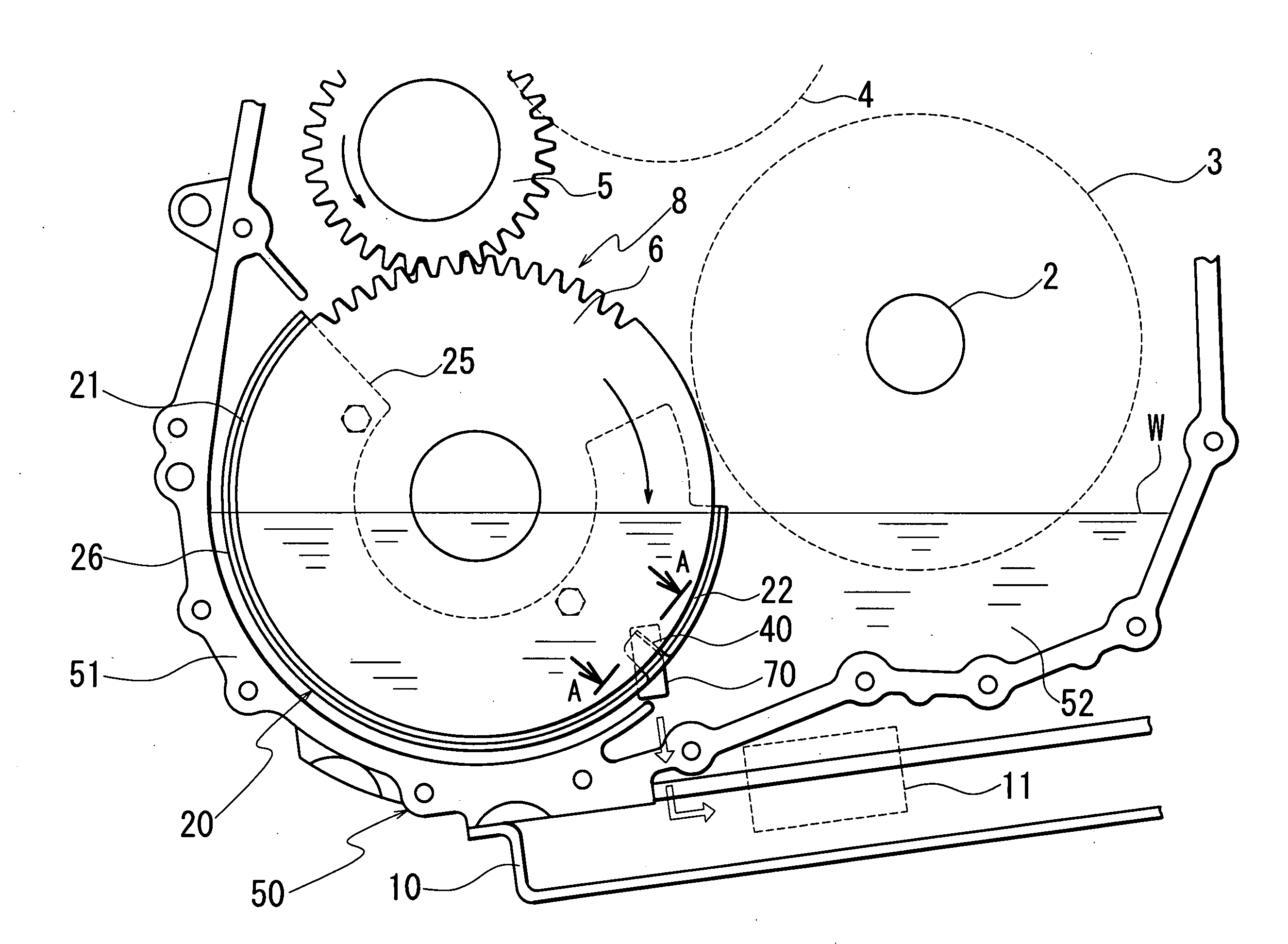
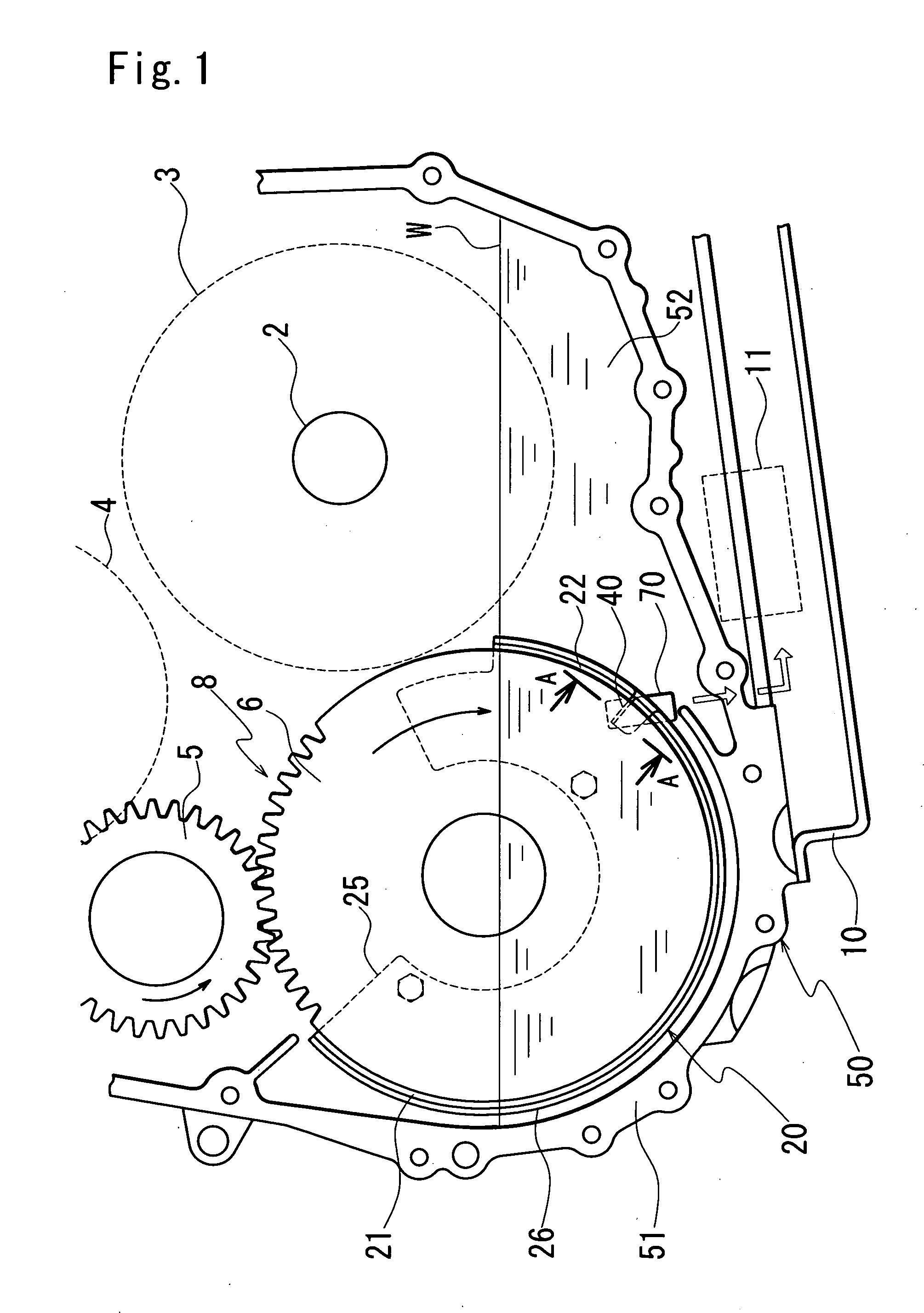
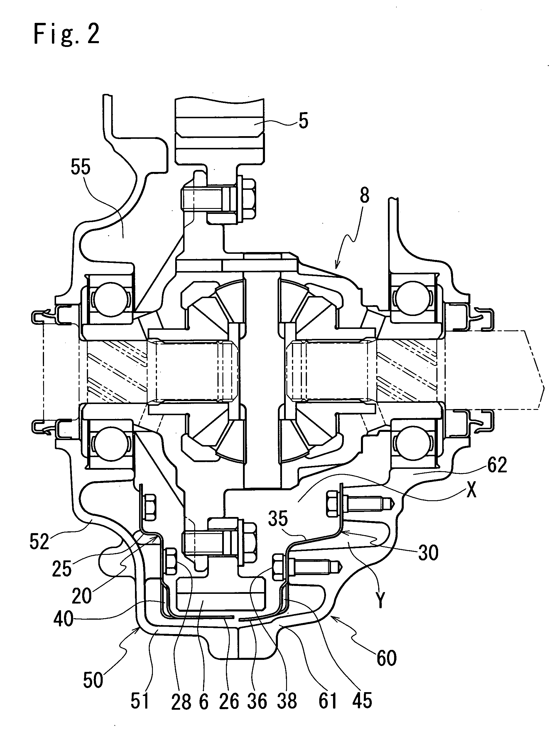
[0021]FIG. 1 is a front view showing a final gear of an automatic transmission seen from a housing side and FIG. 2 is a cross-sectional view showing a differential unit of the automatic transmission.

[0022] Power from an engine is transmitted to an input shaft 2 of an automatic transmission.

[0023] The power transmitted to the input shaft 2, after rotation speeds of the input shaft 2 are converted through a transmission unit including a primary pulley 3 connected to the input shaft 2, a sec...


PUM


Abstract

An oil discharge structure of a baffle plate for discharging oil from a space of a gear side to a space of a transmission side with a space-saving design is provided. A slit is formed in a side face plate facing a final gear of a case side baffle plate to discharge the oil from an oil volume X in the circumference of the final gear to an oil volume Y stored in a clearance between the case side baffle plate and the transmission case, and in a clearance between the housing side baffle plate and the housing. This provides a compact structure that is not larger in a radial direction of the final gear and discharges the oil in the oil volume X.

Description

BACKGROUND OF THE INVENTION [0001] 1. Field of the Invention [0002] The present invention relates to an oil discharge structure of a baffle plate surrounding a rotating body. [0003] 2. Description of the Prior Art [0004] As described in Japanese Utility Model Laid-open Publication No. H1-67374, there has been conventionally used a baffle plate surrounding a rotating body (referred to as “a gear” hereinafter) in an automatic transmission. [0005] The baffle plate separates a space of a gear side from a space of a transmission case side (an oil-storing side) by surrounding a circumference of the gear placed in oil, thereby reducing an amount of the oil stirred by the gear. [0006] An inlet / outlet hole is formed in a lower part of the baffle plate to connect the space of the gear side to the space of the transmission case side so that unnecessary oil stirred by the gear is discharged to the space of the transmission case side. [0007] Hence, a friction loss during rotating of the gear has...

Claims


Application Information

Patent Timeline
Patent Type & Authority Applications(United States)
IPC IPC(8): F16H57/02F16H57/04
CPCF16H57/0423Y10T74/19991Y10T74/2188F16H57/0483
Inventor TAGUCHI, HIROMISUZUKI, HITOSHINAKAJIMA, KATSUYOSHI
Owner JATCO LTD
Why Eureka
Try Eureka