Floating disc brake assembly with interlocking hub and rotor

a technology of floating disc brakes and hubs, applied in the field of disc brakes, can solve the problems of increasing maintenance costs, deteriorating the performance of the entire disc brake assembly, and limited thermal expansion of the rotor during braking, so as to reduce one or both of failures

Inactive Publication Date: 2006-03-09
POWERSPORTS GROUP
View PDF20 Cites 7 Cited by
  • Summary
  • Abstract
  • Description
  • Claims
  • Application Information

AI Technical Summary

Benefits of technology

[0017] In another preferred embodiment, the floating disc brake assembly reduces one or both of failure of the rotor or knockback.
[0019] In another preferred embodiment, the interlocking lobes increase surface area contact between the hub and the rotor.

Problems solved by technology

Otherwise, the braking components will become heated to temperatures at which they will fail, for example, by i) causing vibrations across the disc brake assembly, which can result in rough or irregular braking sensations, or ii) ultimately warping, fracturing, or otherwise deteriorating the hub, the rotor, or other braking components, thereby ultimately deteriorating the performance of the entire disc brake assembly, or increasing the maintenance costs thereof, or worse.
If the rotor is fixed with respect to the hub (i.e., a non-floating disc brake assembly), accommodating thermal expansion of the rotor during braking is limited because of the integrated connection between the rotor and the hub.
This fixed arrangement can create a large thermal gradient and large thermal discrepancies in the rotor, which can induce high thermal stresses and cause the entire disc brake assembly to fail.
Even if the rotor is allowed to float with respect to the hub, however, adequately accommodating thermal expansion of the rotor during braking has also been largely unsatisfactory.

Method used


Image

  • Floating disc brake assembly with interlocking hub and rotor
  • Floating disc brake assembly with interlocking hub and rotor
  • Floating disc brake assembly with interlocking hub and rotor

Examples


Embodiment Construction

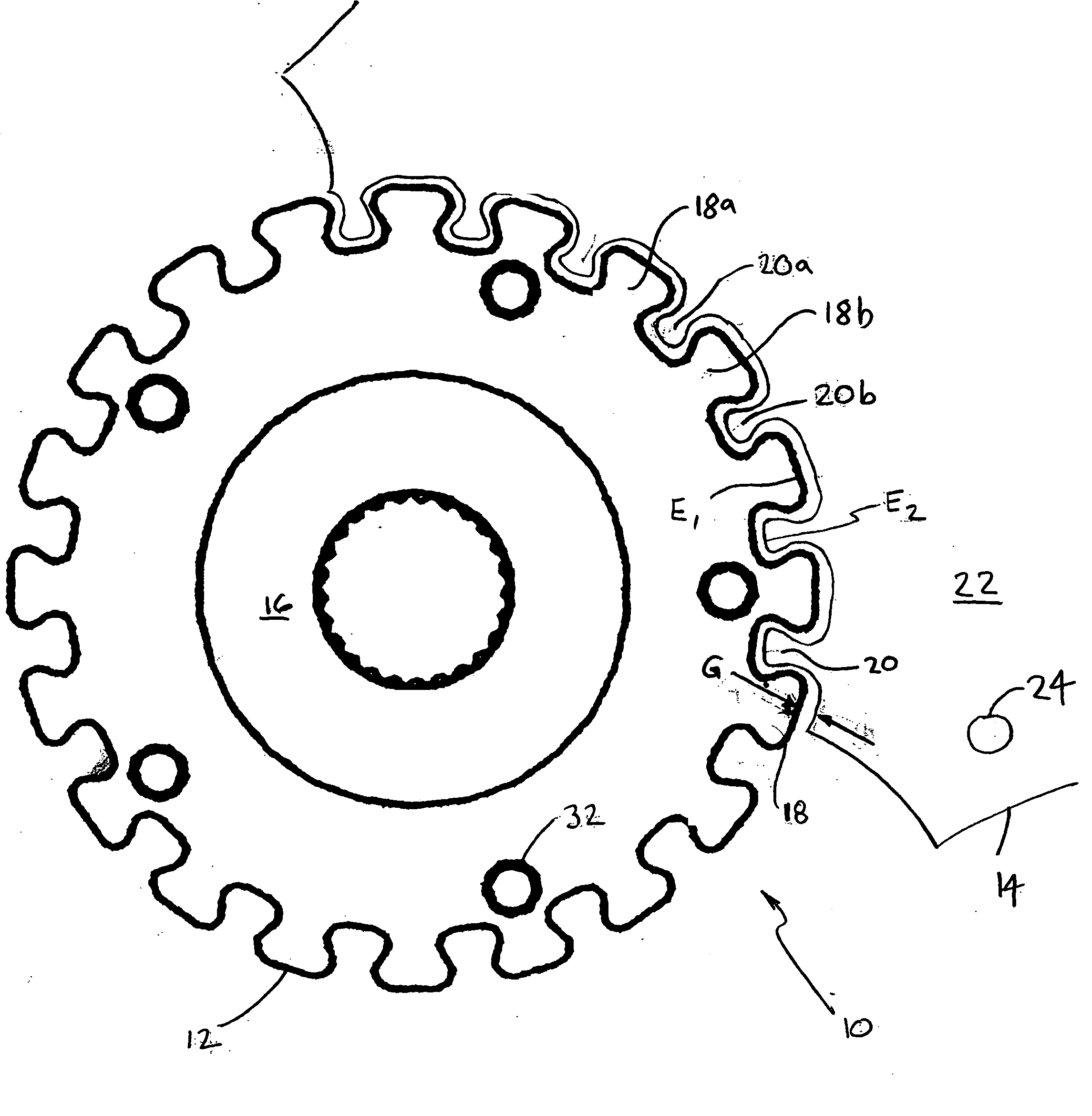
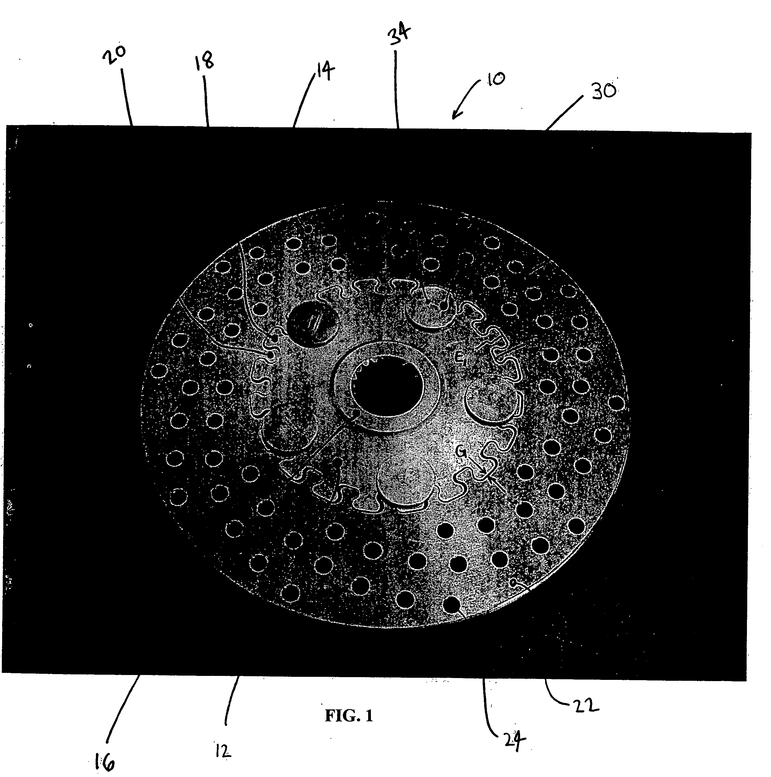
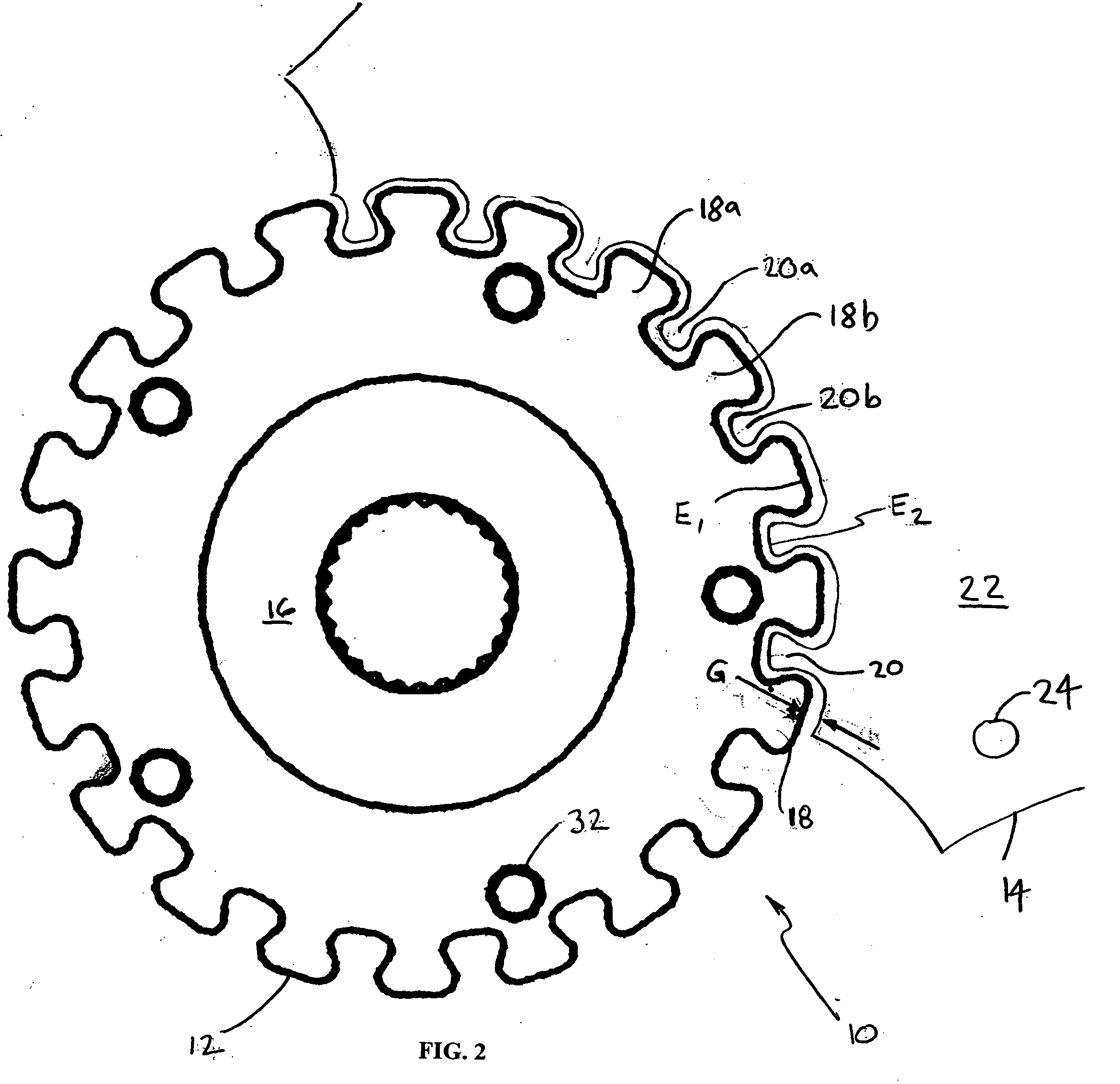
[0030] Referring now to FIG. 1, a first view is provided of a disc brake assembly 10 comprising a brake hub (hereinafter, hub) 12 and a rotor 14. More specifically, both the hub 12 and the rotor 14 are generally semi-circular in shape, with the rotor 14 coupled to, and disposed circumferentially around, the hub 12. As such, the rotor 14 annularly surrounds the hub 12, whereby the hub 12 and the rotor 14 are concentrically arranged about a common axis. Accordingly, the hub 12 and the rotor 14 are floatably connected to one another such that an axis of rotation of the hub 12 is generally the same as, or at least generally aligned with, an axis of rotation of the rotor 14, and vice versa.

[0031] In floating disc brake assemblies 10, the hub 12 and the rotor 14 are separate components. In various embodiments, they can be fabricated or formed from separate materials. And they can be chosen from conventional forms and materials commonly used in braking applications. For example, they can ...


PUM


Abstract

A floating disc brake assembly comprises a hub and a rotor in mating alignment therewith through one or more interlocking lobes that are alternatingly arranged about an outer peripheral edge of the hub and an internal edge of the rotor. The rotor is coupled to, and disposed circumferentially around, the hub. As a friction element is applied to the rotor to decrease rotation thereof during a braking operation, the interlocking lobes transmit brake torque from the rotor to the hub through a gap existing therebetween. The gap retards heat flow. The gap also permits radial float. Differing hub and rotor widths, or a floating clearance between a fastener and the hub, both permit axial float. Warpage and knockback of the rotor are reduced.

Description

CROSS-REFERENCES TO RELATED APPLICATIONS [0001] This application claims priority under 35 U.S.C. § 119(e) to U.S. Provisional Patent Application Ser. No. 60 / 555,842, filed on Mar. 24, 2004, the entire disclosure of which is hereby incorporated by reference.STATEMENT REGARDING FEDERALLY SPONSORED RESEARCH OR DEVELOPMENT REFERENCE TO MICROFICHE APPENDIX BACKGROUND OF THE INVENTION [0002] 1. Field of the Invention [0003] This invention relates to disc brakes, and, more specifically, to floating disc brake assemblies, as commonly used, for example, with motorized vehicles such as snowmobiles, ATVs, and the like. [0004] 2. Description of Related Art [0005] Many types of disc brakes are well-known, including, for example, floating disc brake assemblies comprising a hub and a floating rotor. [0006] As with all mechanical braking systems, disc brake assemblies retard rotary motion of a rotor—which, in turn, usually retards rotary motion of an axle shaft connected thereto—by converting mecha...

Claims


Application Information

Patent Timeline
Patent Type & Authority Applications(United States)
IPC IPC(8): F16D65/12
CPCF16D65/12F16D65/123F16D2065/1308F16D2065/1396F16D2065/1368F16D2065/1376F16D2065/136
Inventor JACOB, WILLIAM V.
Owner POWERSPORTS GROUP
Why Eureka
Try Eureka