Rear wing structure for remote-controlled flight assuring fast and stable turning

a technology of rear wing and remote control, which is applied in the direction of remote control toys, toys, ornithopters, etc., can solve the problems of changing the angle of attack of the body and main wings, changing drag, etc., and achieves the effect of easy and stably controlling the fligh

Inactive Publication Date: 2006-03-09
NEUROS
View PDF10 Cites 15 Cited by
  • Summary
  • Abstract
  • Description
  • Claims
  • Application Information

AI Technical Summary

Benefits of technology

[0010] Therefore, in an ornithopter type flight controlled by the remote controller, a hori...

Problems solved by technology

This change of the drag area leads to the change of drag,...

Method used


Image

  • Rear wing structure for remote-controlled flight assuring fast and stable turning
  • Rear wing structure for remote-controlled flight assuring fast and stable turning
  • Rear wing structure for remote-controlled flight assuring fast and stable turning

Examples


Embodiment Construction

[0022] Now, the present invention will be explained with reference to the accompanying drawings.

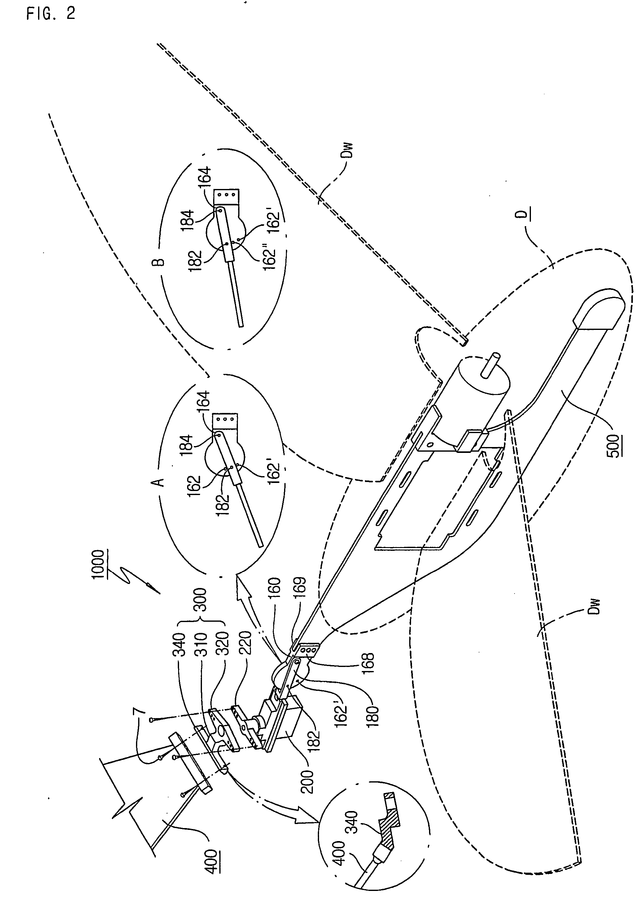
[0023]FIG. 2 shows a horizontal rear wing structure 1000 of an remote-controlled flight according to the present invention.

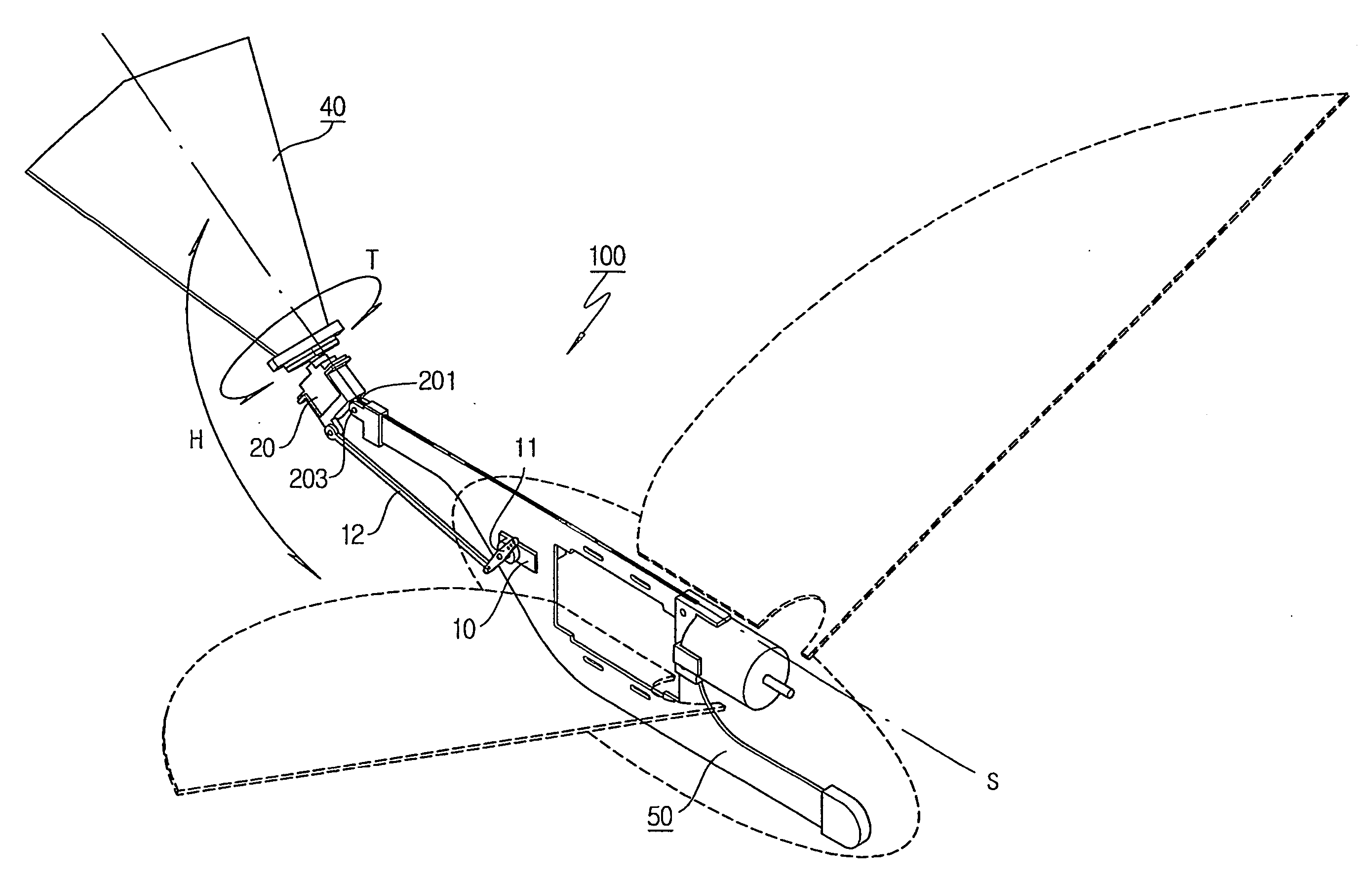
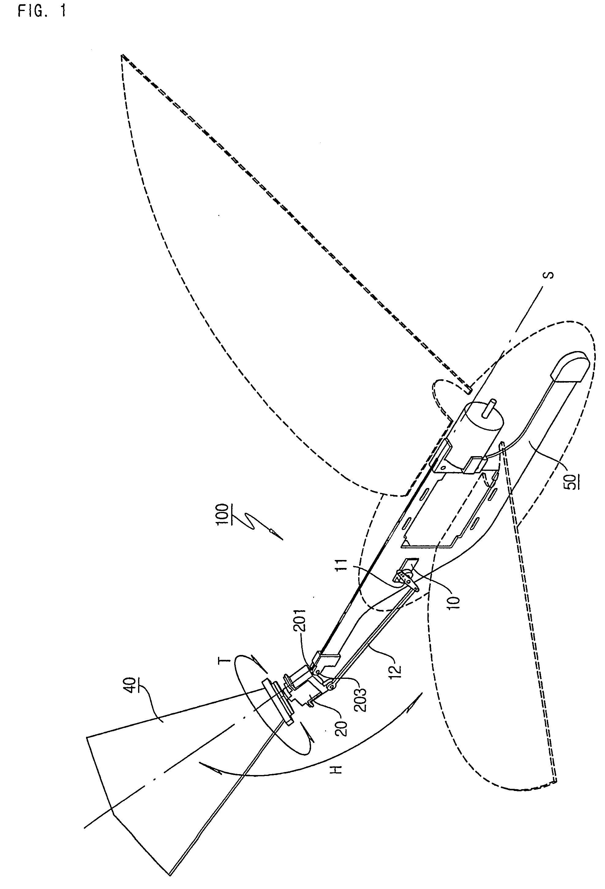
[0024] Firstly, within a body D having the right and left main wings Dw, panel 500 is provided and a servo motor holder 200 is combined with the panel 500 in the rear part of the panel 500.

[0025] A horizontal rear wing 400 is connected with the servo motor in the holder 200 by means of a connection for plane-rotation so that the horizontal rear wing 400 rotates with respect to the plane (P in FIG. 3) of the body.

[0026] The connection for plane-rotation includes a rotating member 220 mounted on the rotating shaft of the servo motor in the holder 200 and a connecting part 300 which connects the rotating member 220 with the horizontal rear wing 400.

[0027] The rotating member 220 is arranged to face the upper side of the body and the connecting part 300 is mounted on...


PUM


Abstract

The present invention provides a horizontal rear wing structure of a remote controlled flight assuring fast and stable turning. The horizontal rear wing structure 1000 includes a servomotor facing the upper side of the flight body D, a rotating member 220 mounted on the servomotor and a connecting part 300 mounted on the top side of the rotating member, the connecting part being combined with the horizontal rear wing. Accordingly, the horizontal rear wing 400 rotates with respect to the plane of the flight body.

Description

FIELD OF THE INVENTION [0001] The present invention relates to a rear wing structure for remote-controlled flight assuring fast and stable turning. The present invention shows an ornithopter type flight, however, the invention is not limited thereto. BACKGROUND [0002] There is an ornithopter type flight. This type of flight includes the right and left main wings which are connected with an electrical motor through a connecting rod and gear train so that the operation of the motor causes the flapping motion of the right and left main wings. The flapping motion generates a thrust and a lift and the flight can fly. This type of flight needs a horizontal rear wing to obtain a necessary lift. When the horizontal rear wing is adjusted to be raised, the vertical component of the reaction due to the flapping motion of the main wings acts as the lift. [0003] This type of flight may achieve its turning by means of a vertical rear wing. The rotation of the vertical rear wing to the right or le...

Claims


Application Information

Patent Timeline
IPC IPC(8): B64C33/02A63H27/00A63H27/18A63H30/00
CPCA63H30/00A63H27/008A63H30/04A63H27/00
Inventor KIM, SEUNG-WOOJANG, IL-HYUNG
Owner NEUROS
Why Eureka
Try Eureka