Multi-fit hitch assembly with selectively positionable mounting flanges

a technology of mounting flanges and hitches, applied in the field of multi-fit receiver assemblies, can solve the problems of affecting the rigidity of the apparatus, being relatively complicated,

Inactive Publication Date: 2006-03-09
HORIZON GLOBAL AMERICAS INC
View PDF17 Cites 6 Cited by
  • Summary
  • Abstract
  • Description
  • Claims
  • Application Information

AI Technical Summary

Benefits of technology

[0007] Specifically, the receiver includes selectively positionable mounting flanges and mounting brackets adapted to provide enhanced versatility when mounting the trailer hitch receiver to the frame of a towing vehicle. Further, these flanges and brackets are relatively low profile, single-piece components that are relatively inexpensive to manufacture and easy to use. Unlike telescoping tubular components that have a relatively wide profile, these mounting flanges and mounting brackets provide the necessary clearance to fit in tight areas around vehicle components and, as such, are more functional and suited to many more applications. While allowing the necessary adjustability, the flanges and brackets also ensure a rigid connection.
[0008] Advantageously, the flanges may be positioned at substantially any point along the length of the cross member of the receiver. Accordingly, the spacing between the flanges may be adjusted to provide a customized fit with the frame of the vehicle to which the receiver is to be mounted. As a result, one receiver is capable of being mounted to more makes and models of vehicles. The brackets of the receiver may also be selectively positioned both fore or aft and inboard or outboard to provide relative adjustment in two perpendicular directions. This ability provides substantial versatility and allows the mounting of the receiver to an even wider range of vehicles.
[0012] More specifically, the first mounting flange engages and holds the first mounting bracket and the second mounting flange engages and holds the second mounting bracket. Advantageously, the pair of opposed mounting brackets may be selectively mounted either inboard or outboard of the first and second mounting flanges. A notch is also provided in the peripheral edge of each mounting bracket. That notch provides the necessary clearance around the cross member to allow mounting of the mounting brackets in the rearmost position on the cross member.
[0016] Fore and aft adjustment is provided by the selective mounting of the mounting brackets with the anchoring apertures aligned with either the first or second set of mounting apertures. Together, the side to side or transverse and fore and aft or longitudinal adjustment provided by the receiver of the present invention allow a great deal of versatility in mounting the receiver around exhaust and suspension systems of a towing vehicle. They even allow mounting in vehicles of different frame width. Accordingly, a receiver of the present invention may be conveniently and effectively mounted to a wide variety of vehicle models even when those models are equipped with a wide variety of equipment options or accessories. As such, the receiver of the present invention provides multi-fit capability allowing its use for a wide number of towing applications. Of course, since one receiver meets the requirements of numerous applications, it is unnecessary to custom manufacture a receiver for each such application. Thus, manufacturing costs are substantially reduced not only to the benefit of the manufacturer, but also to the ultimate benefit of the purchaser.

Problems solved by technology

The apparatus is, however, relatively complicated and includes a number of parts to allow adjustability while providing for the mounting of the main frame member.
Further, a telescoping tubular construction is used and this introduces substantial play into the arrangement resulting in a detrimental loss in rigidity.

Method used


Image

  • Multi-fit hitch assembly with selectively positionable mounting flanges
  • Multi-fit hitch assembly with selectively positionable mounting flanges
  • Multi-fit hitch assembly with selectively positionable mounting flanges

Examples


Embodiment Construction

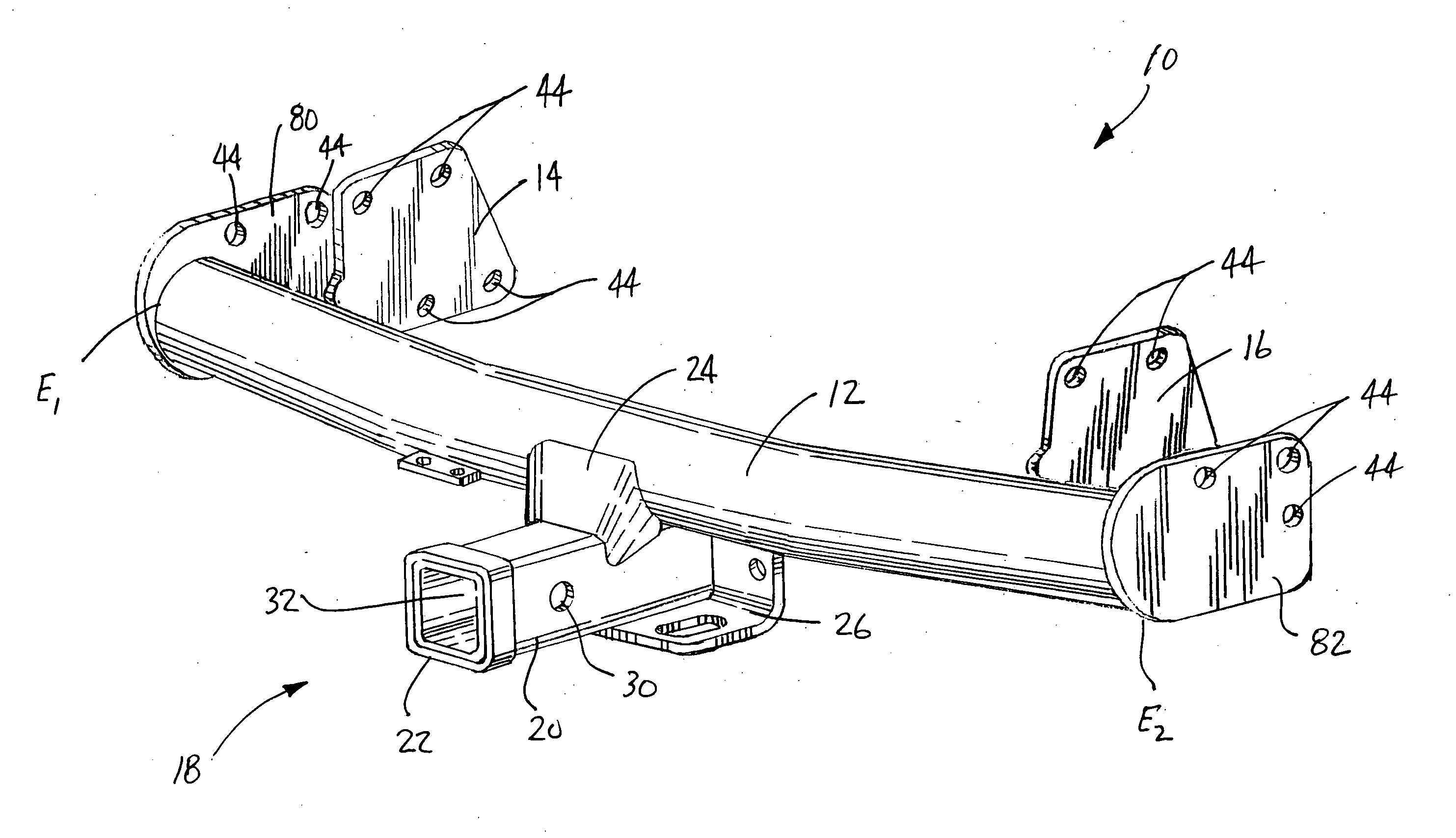
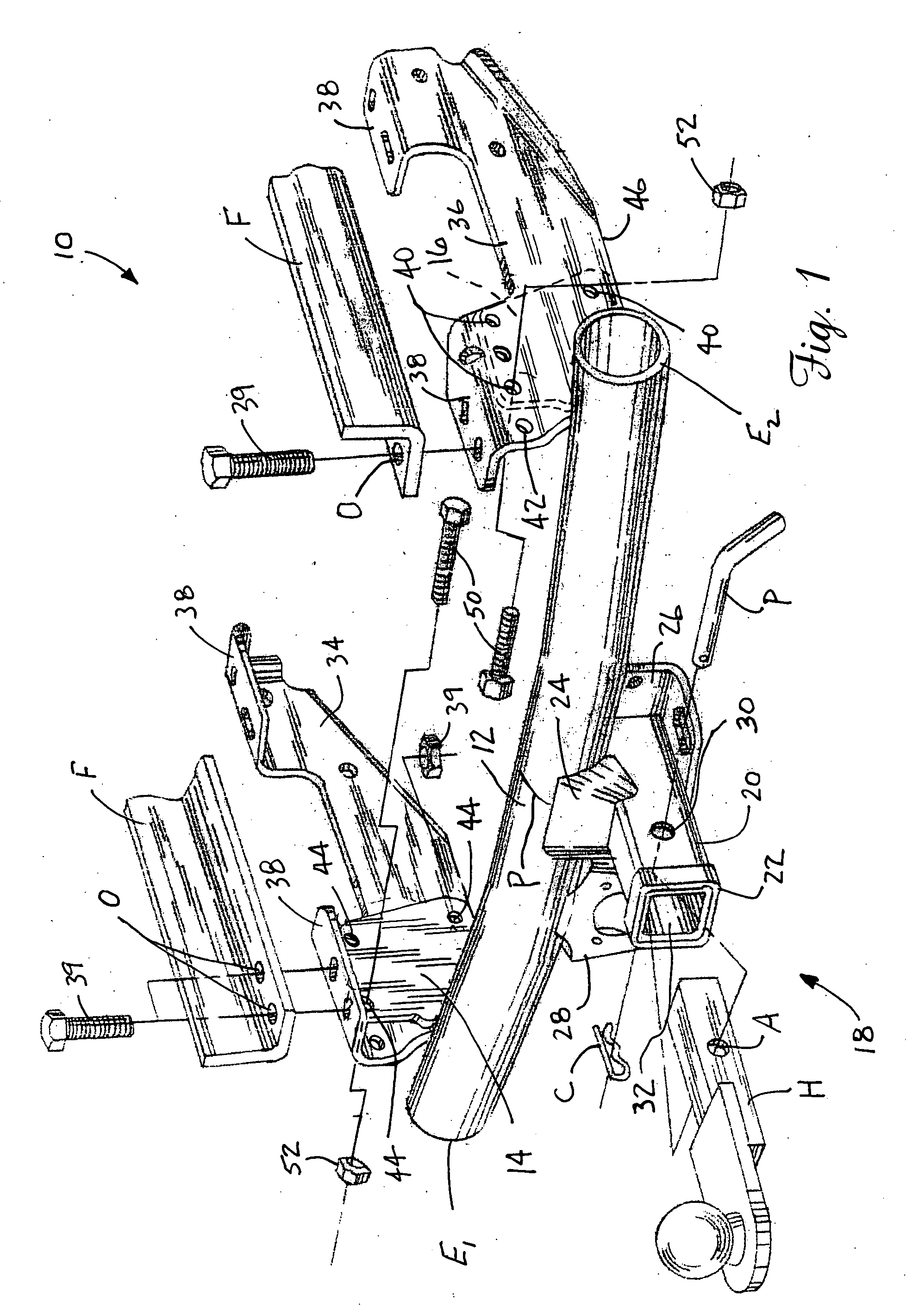
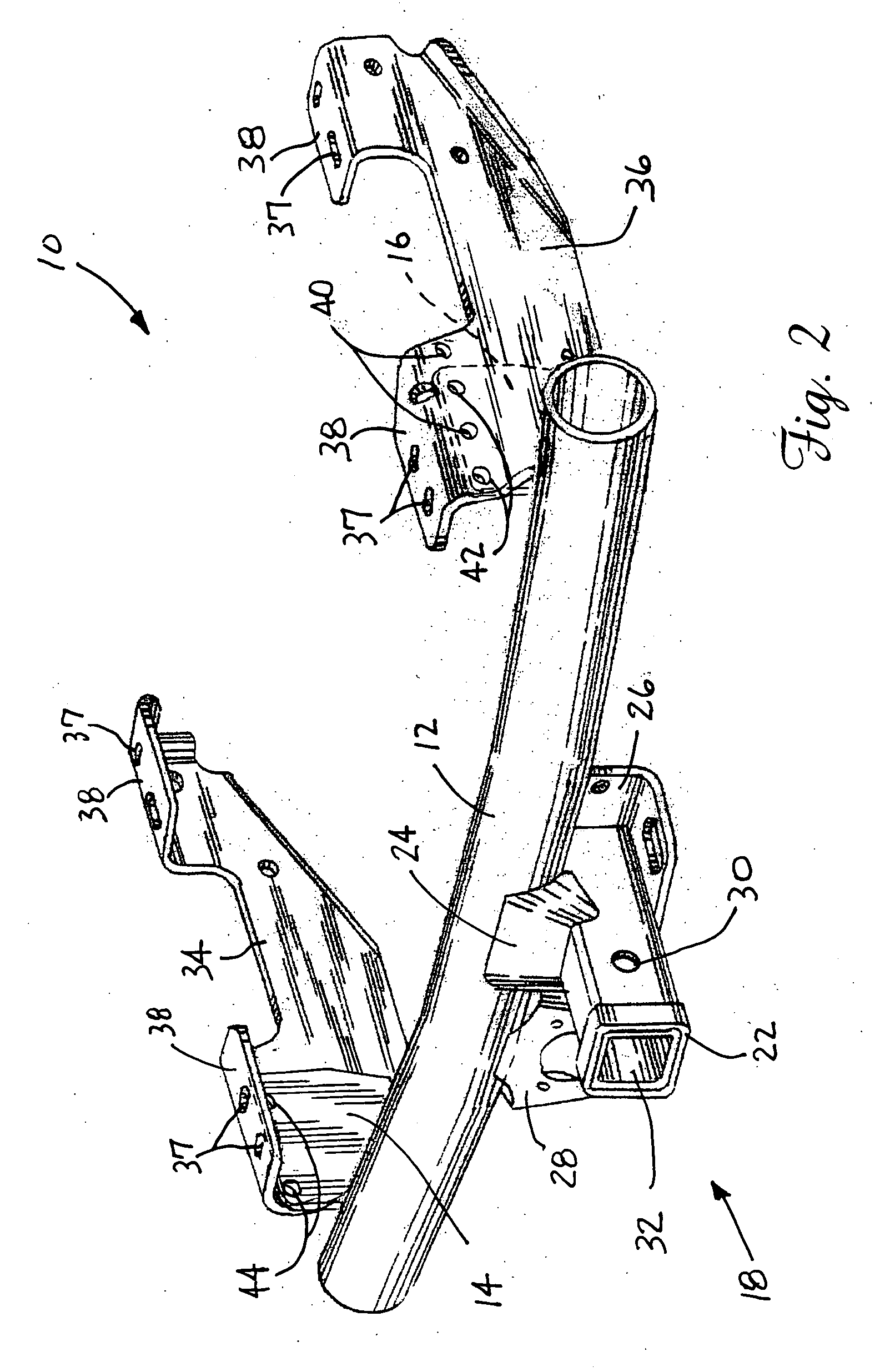
[0026] Reference is now made to FIG. 1 showing the trailer hitch receiver 10 of the present invention. The trailer hitch receiver 10 includes a main frame member 11 preferably formed from tubular steel material. As clearly illustrated, the main frame member 11 includes a cross member 12 that may have a round cross section. The cross member 12 includes a first end E1, a second end E2 and a midpoint P.

[0027] A first selectively positionable mounting flange 14 is secured to the cross member 12 at a selected first point between the first end E1 and the midpoint P of the cross member. Similarly, a second mounting flange 16 is secured to the cross member 12 at a selected second point between the second end E2 and midpoint P of the cross member. Advantageously, by altering or adjusting the positioning of the two flanges 14, 16 along the cross member 12, the spacing between them may be varied to provide a custom fit with the frame of substantially any towing vehicle.

[0028] Each mounting f...


PUM


Abstract

The present invention relates to a trailer hitch receiver including a cross member, a first mounting flange carried on the cross member between the midpoint and a first end thereof and a second mounting flange carried on the cross member between the midpoint and a second end thereof. The trailer hitch receiver also includes a pair of opposed mounting brackets. Each of the opposed mounting brackets includes a first mounting arrangement or series of apertures that secures the mounting brackets to the cross member in a first position and a second mounting arrangement or second set of mounting apertures for securing the mounting brackets to the main frame member in a second position.

Description

[0001] This application is a continuation-in-part of pending U.S. patent application Ser. No. 10 / 660,995 filed Sep. 12, 2003, which is a continuation of U.S. patent application Ser. No. 10 / 459,272 filed Jun. 11, 2003 which is a continuation of U.S. patent application Ser. No. 09 / 865,277 filed May 25, 2001, now issued U.S. Pat. No. 6,578,864 which is a continuation of U.S. patent application Ser. No. 09 / 431,588 filed Nov. 1, 1999 now abandoned.TECHNICAL FIELD [0002] The present invention relates generally to the towing field and, more particularly, to a multi-fit receiver assembly providing unmatched mounting versatility so as to allow multiple application use. BACKGROUND OF THE INVENTION [0003] It has long been known to construct trailer hitches that are mounted to vehicles in order to allow the towing of trailers or the like. In recent years, such trailer hitches have been designed to include a central frame member or crossbar carrying mounting brackets at each end thereof for moun...

Claims


Application Information

Patent Timeline
Patent Type & Authority Applications(United States)
IPC IPC(8): B60D1/14
CPCB60D1/52B60D1/485
Inventor MARVIN L., HANSONMCCOY, RICHARD W.SCRUGGS, MARK P.
Owner HORIZON GLOBAL AMERICAS INC
Why Eureka
Try Eureka