Method and apparatus for an improved micro electro-mechanical display backplane
- Summary
- Abstract
- Description
- Claims
- Application Information
AI Technical Summary
Benefits of technology
Problems solved by technology
Method used
Image

Examples
Embodiment Construction
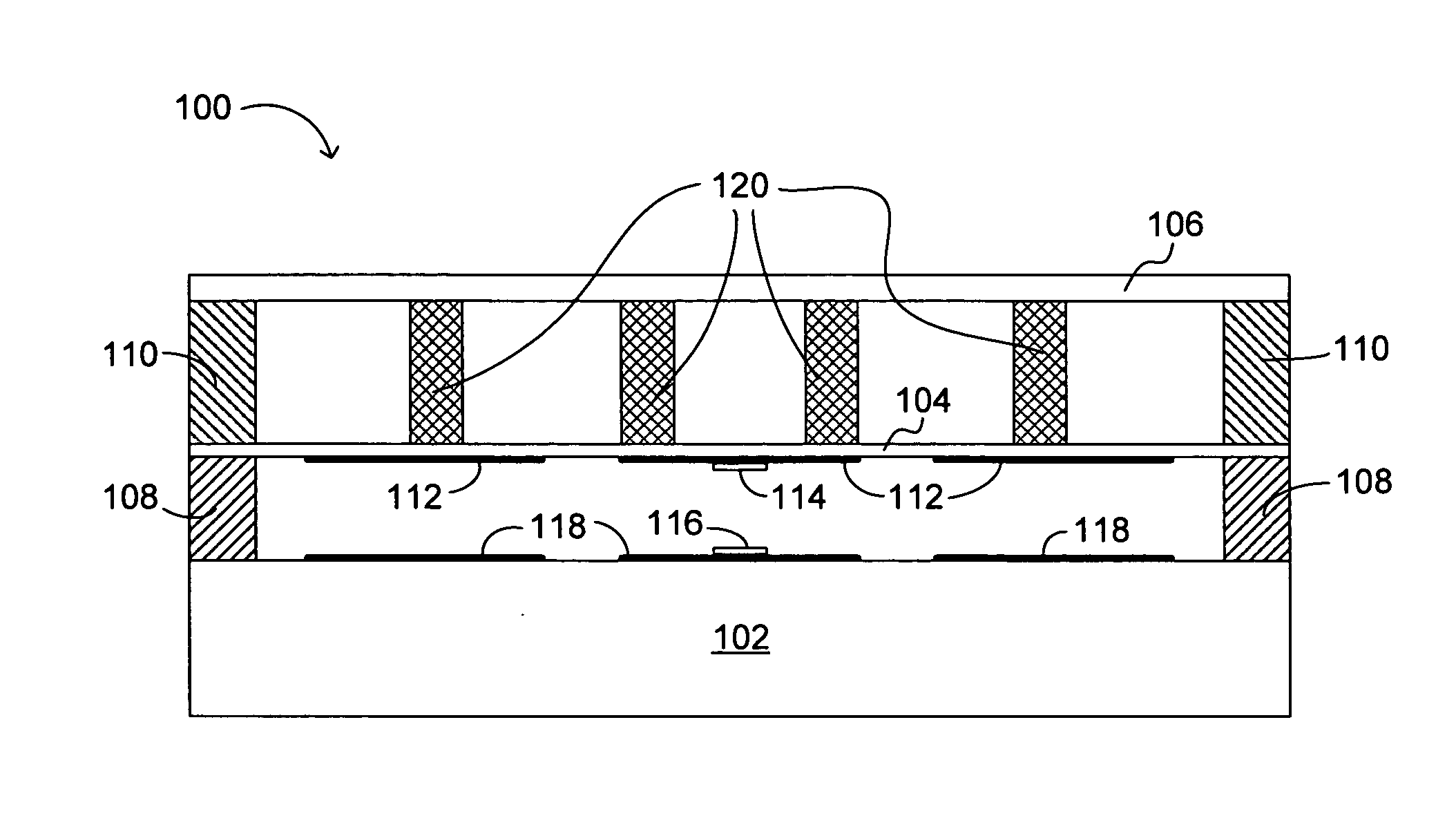
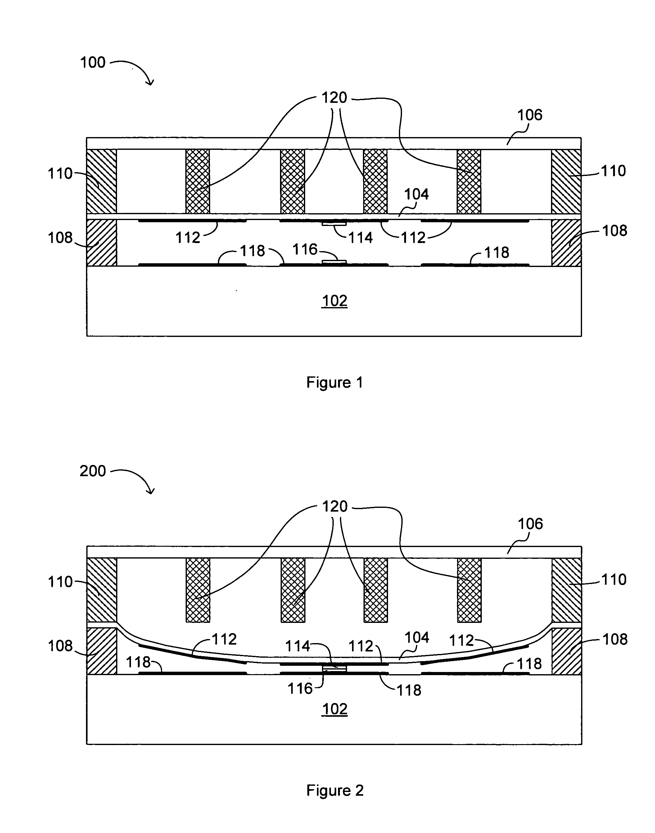
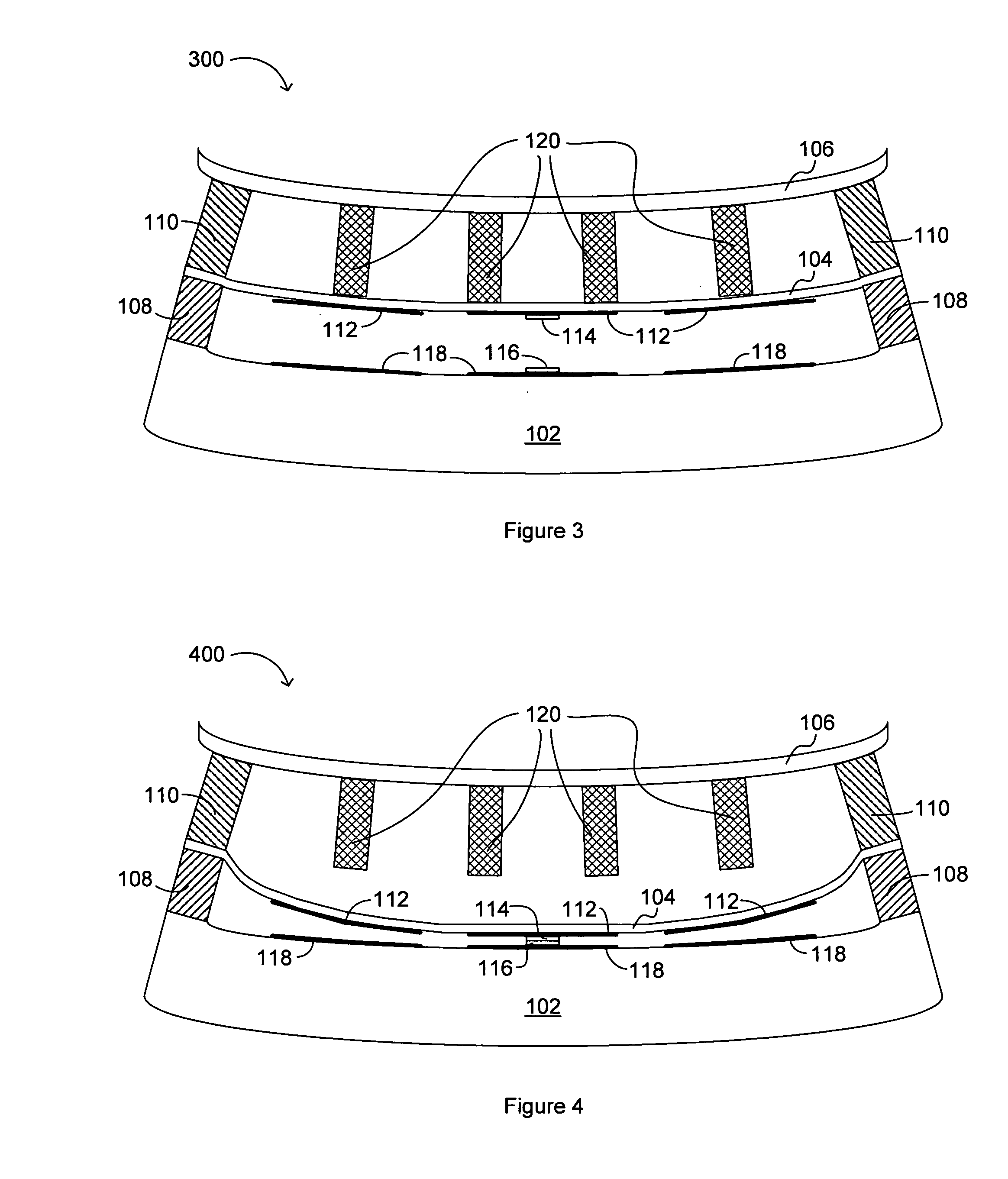
[0010] Embodiments of the present invention provide a micro electromechanical (MEM) backplane component structure suitable for enhanced display mechanical flexibility. Further, the MEM backplane can be manufactured using materials and / or techniques so as to substantially reduce the concentration of potentially damaging components. A matrix of MEM switches can be incorporated into the backplane structure of an optical display.
[0011] In one embodiment, a display system can include a first membrane and second membrane maintained in a spaced apart relationship by a first intermediate layer that can also define cells in a matrix arrangement. Each such cell can form a pixel or a portion of a pixel in a particular display application. A third membrane can also be coupled to the first membrane, either directly, or through a second intermediate layer. Such a second intermediate layer can include a plurality of buffer structures that can maintain the spaced apart relationship when the displa...
PUM
 Abstract
Description
Claims
Application Information
 - Generate Ideas
- Intellectual Property
- Life Sciences
- Materials
- Tech Scout
- Unparalleled Data Quality
- Higher Quality Content
- 60% Fewer Hallucinations
Browse by: Latest US Patents, China's latest patents, Technical Efficacy Thesaurus, Application Domain, Technology Topic, Popular Technical Reports.
© 2025 PatSnap. All rights reserved.Legal|Privacy policy|Modern Slavery Act Transparency Statement|Sitemap|About US| Contact US: help@patsnap.com