
Mobile wireless camera system

a wireless camera and wireless technology, applied in the field of mobile wireless camera systems, can solve the problems of increasing the cost of the system, prone to damage, and not only expensive to install

Inactive Publication Date: 2006-03-09
LANG MEKRA NORTH AMERICA LLC
View PDF7 Cites 39 Cited by
  • Summary
  • Abstract
  • Description
  • Claims
  • Application Information

AI Technical Summary

Problems solved by technology

These are not only expensive to install, in particular when retrofitting existing vehicles, but are also prone to damage.
The plug required for this constitutes another weak point prone to damage or disturbance and raises the cost of the system.
In that case, however, other radio signals may interfere with the image and / or control signals of the camera system.
Thus, if several cameras are installed on a utility vehicle and transmit or receive their image or control signals on the same transmission channel, a malfunction occurs.

Method used


Image

  • Mobile wireless camera system
  • Mobile wireless camera system
  • Mobile wireless camera system

Examples


Embodiment Construction

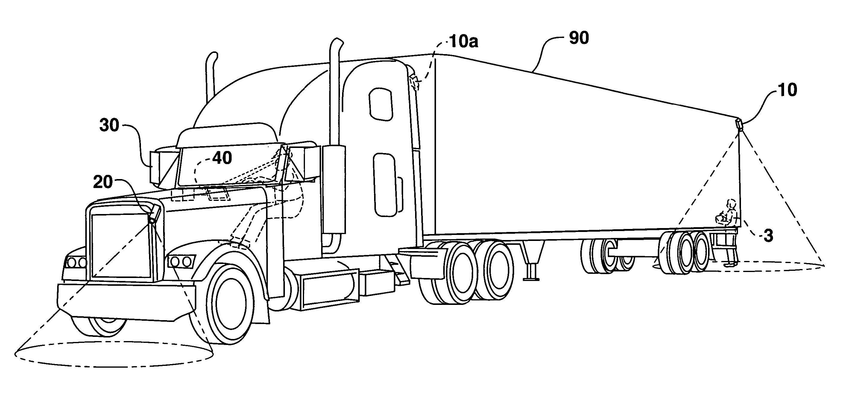
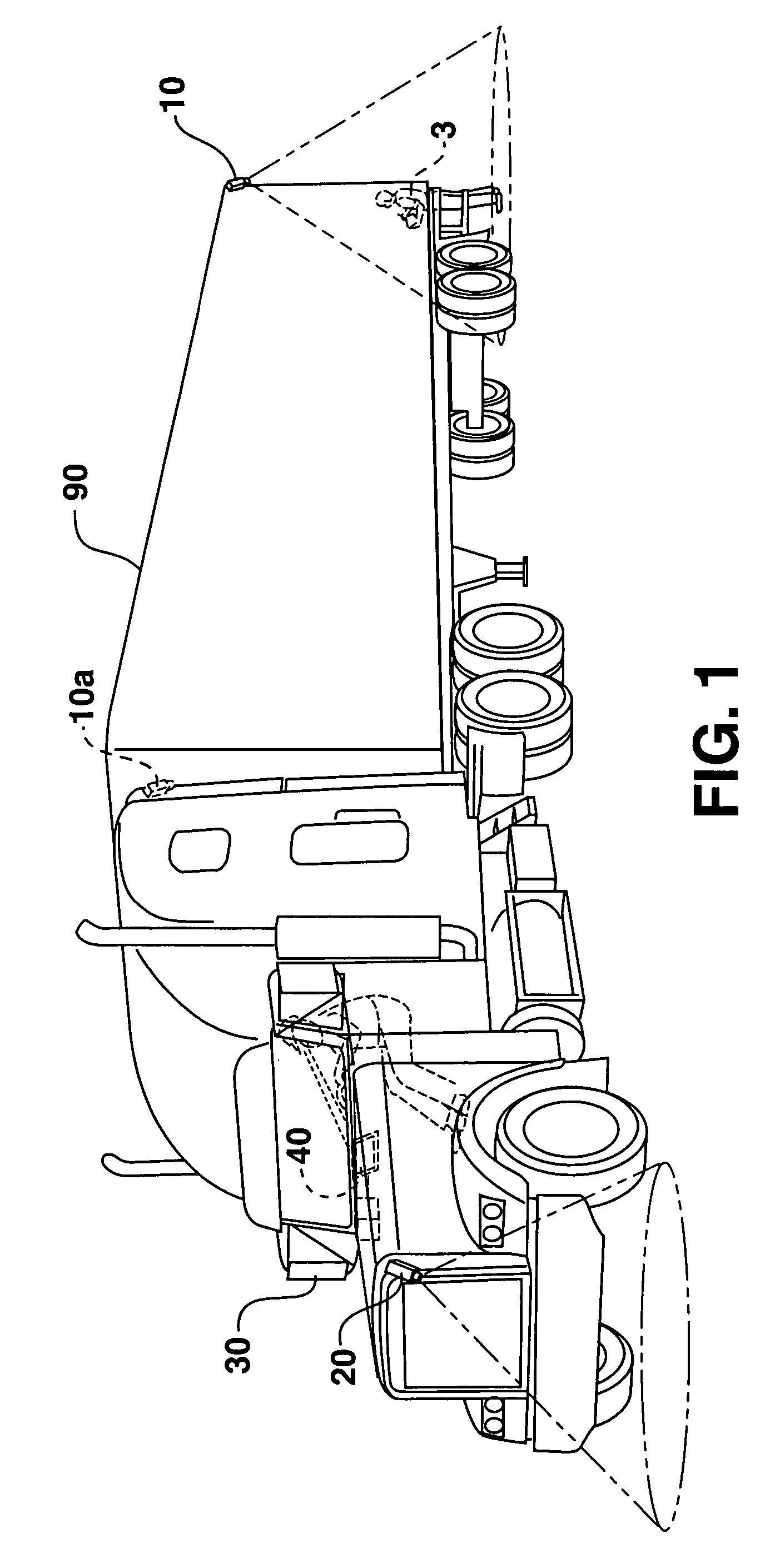
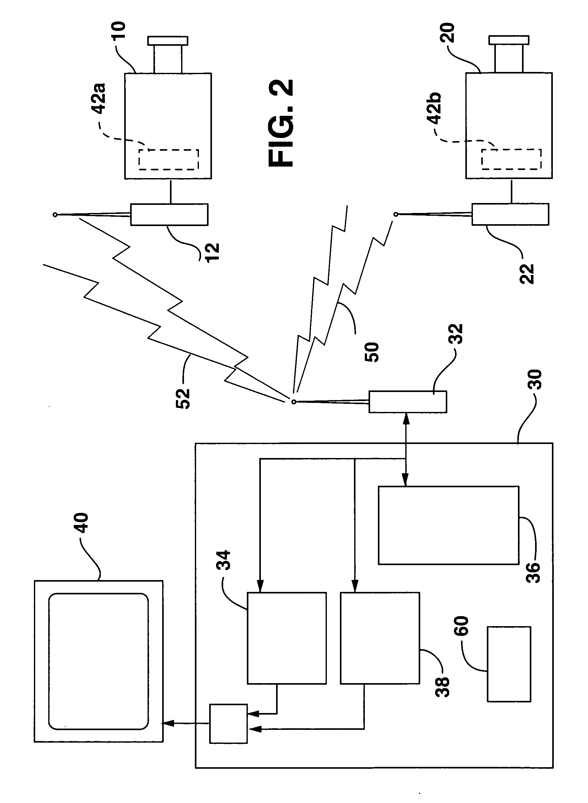
[0013] A mobile wireless camera system for commercial vehicles allowing the driver of the commercial vehicle to see areas surrounding the commercial vehicle is shown in FIGS. 1 and 2. Similarly, the camera system can also be used with agricultural utility vehicles, construction machines etc. A camera system according to the invention can also be used for the monitoring of processes or areas in industry, in the home or for leisure activities. The embodiment represented here shows only one example of an application.

[0014] A first camera 10 is connected to a first camera transceiver 12 for capturing images and transmitting a first image signal representing the captured images. Camera 10 can be attached to the associated commercial vehicle 90 by a quick-mounting device. Suitable quick-mounting devices may include bayonet or snap-on connections, magnetic holders or screw connections.

[0015] Further, the first camera 10 can also be installed by means of the quick-mounting device on the t...


PUM


Abstract

A mobile wireless camera system for commercial vehicles allowing the driver of the commercial vehicle to see areas surrounding the commercial vehicle using first and second cameras connected to first and second camera transceivers for capturing images and transmitting a first and second image signals representing the captured images. The system uses a controller in communication with a control transceiver for setting an ID code in each camera and for selecting a camera for viewing. The camera transceivers transmit the ID code along with the image signals. The controller uses an ID code recognition unit for identifying whether the ID code is the ID code of the selected camera. The controllers allows transmission of images if the received ID code and the ID code of the selected camera are the same.

Description

FIELD OF THE INVENTION [0001] The present invention relates to a mobile camera system with wireless signal transmission, in particular for utility vehicles, as well as a process for such a system. BACKGROUND [0002] Camera systems are often used for monitoring areas that are difficult or impossible to see. The German patent application bearing file number 10234483.3 discloses a video camera at the rear of a truck for the monitoring of the rear area. A monitor enables the driver, as he drives in reverse, to approach loading ramps in reverse and to recognize obstacles behind the vehicle in time. Similarly, cameras can be used to monitor so-called “blind spots” or areas in front of the vehicle. [0003] The image signals of the camera are transmitted by means of continuous data conduits, in particular metal or glass fiber cables. These are not only expensive to install, in particular when retrofitting existing vehicles, but are also prone to damage. Especially in the case of utility vehic...

Claims


Application Information

Patent Timeline
IPC IPC(8): H04N7/18H04N9/47H04N7/24
CPCB60R1/00B60R2300/101B60R2300/105B60R2300/404B60R2300/406H04N7/181H04N21/6587H04N21/235H04N21/4223H04N21/42684H04N21/435H04N21/43637H04N21/2187B60R1/28B60R1/23
Inventor LANG, HEINRICHEMMERT, HARALDKIESENBAUER, HERMANNWITZKE, MICHAEL
Owner LANG MEKRA NORTH AMERICA LLC
Learn More