Fixing device, image forming apparatus including the fixing device, and fixing method

a technology of fixing rollers and fixing rollers, which is applied in the direction of electrographic process equipment, instruments, optics, etc., can solve the problems of reducing the temperature of the center portion of the fixing roller in its axial direction, and causing the fixing roller to overheat, and achieves the effect of small width and large width

Active Publication Date: 2006-03-09
RICOH KK
View PDF21 Cites 75 Cited by
  • Summary
  • Abstract
  • Description
  • Claims
  • Application Information

AI Technical Summary

Benefits of technology

[0016] According to yet another aspect of the present invention, a method of fixing an image formed on a recording material includes heating around a center portion of a first rotary member in an axial direction of the first rotary member by a center portion heating member; heating around end portions of the first rotary member in the axial direction of the first rotary member by an end portion heating member; heating a substantially full width of the first rotary member including the center portion and the end portions by a full width heating member; conveying the recording material having an image through a nip part formed between the first rotary member and a second rotary member; detecting a temperature of the center portion of the first rotary member; detecting a temperature of at least one of the end portions of the first rotary member; first controlling a heating amount of the full width heating member based on the detected temperature of the center portion of the first rotary member when a plurality of recording materials each having a relatively large width in a direction perpendicular to a conveying direction of the recording material consecutively pass through the nip part between the first rotary member and the second rotary member; and second controlling the heating amount of the full width heating member based on the detected temperature of the at least one of the end portions of the first rotary member when a plurality of recording materials each having a relatively small width in a direction perpendicular to a conveying direction of the recording material consecutively pass through the nip part between the first rotary member and the second rotary member.

Problems solved by technology

Further, when a plurality of recording materials each carrying an image and having a small width in a direction perpendicular to a conveying direction of the recording material consecutively pass through the fixing device, the temperature of a center portion of the fixing roller in its axial direction decreases; however, end portions of the fixing roller in its axial direction where the recording material having the small width does not pass through typically overheat.

Method used


Image

  • Fixing device, image forming apparatus including the fixing device, and fixing method
  • Fixing device, image forming apparatus including the fixing device, and fixing method
  • Fixing device, image forming apparatus including the fixing device, and fixing method

Examples


Embodiment Construction

[0034] Non-limiting embodiments of the present invention are now described with reference to the drawings, wherein like reference numerals designate identical or corresponding parts throughout the several views.

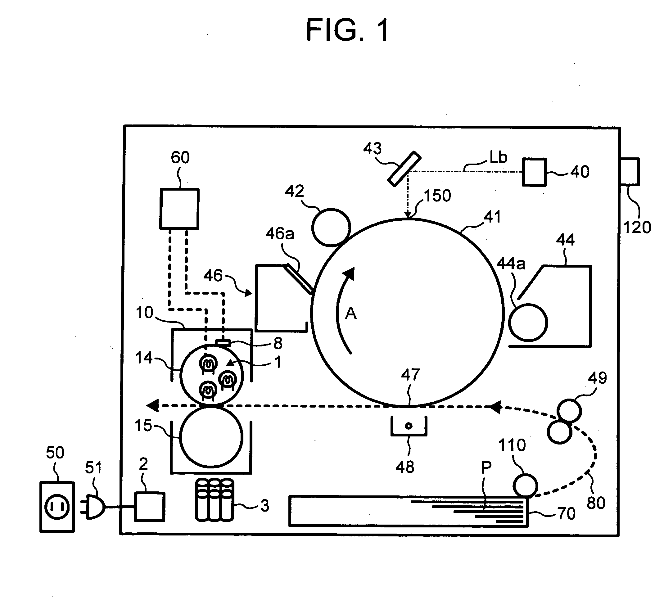
[0035]FIG. 1 is a schematic cross sectional view of an image forming apparatus including a fixing device according to an embodiment of the present invention. The image forming apparatus may be a copying machine, a printer, a facsimile machine, or other similar image forming apparatuses. The image forming apparatus includes a drum-shaped photoreceptor 41 acting as an image carrier. Arranged around the photoreceptor 41 are a charging device 42, a mirror 43, a developing device 44, a transfer device 48, and a cleaning device 46 in the order of the rotational direction of the photoreceptor 41 indicated by an arrow A in FIG. 1. Specifically, the charging device 42 includes a charging roller. The mirror 43 constitutes a part of an exposure device 40. The developing device 44 inclu...


PUM


Abstract

A fixing device for fixing an image formed on a recording material includes first and second rotary members having a nip part therebetween, a heating part that heats the first rotary member, a center portion temperature detecting unit that detects a temperature of a center portion of the first rotary member, and an end portion temperature detecting unit that detects a temperature of an end portion of the first rotary member. When recording materials each having a relatively large width consecutively pass through the nip part, a control unit controls a heating amount of a full width heating member based on the temperature detected by the center portion temperature detecting unit, and when recording materials each having a relatively small width consecutively pass through the nip part, the control unit controls the heating amount of the full width heating member based on the temperature detected by the end portion temperature detecting unit.

Description

CROSS-REFERENCE TO RELATED APPLICATIONS [0001] This application claims priority to Japanese Patent Application No. 2004-262589 filed in the Japanese Patent Office on Sep. 9, 2004, the entire contents of which is hereby incorporated herein by reference. BACKGROUND OF THE INVENTION [0002] 1. Field of the Invention [0003] The present invention relates to a fixing device and a fixing method in which an image is fixed onto a recording material while supplying power to a heating part of a fixing roller from a power storage unit, and to an image forming apparatus including the fixing device. [0004] 2. Discussion of the Related Art [0005] A fixing device that fixes a toner image formed on a recording material, such as a recording sheet, via a heating part having a main heating element and an auxiliary heating element has been widely used. In such a background fixing device, the main heating element is powered by a main power supply unit, and the auxiliary heating element is powered by an au...

Claims


Application Information

Patent Timeline
Patent Type & Authority Applications(United States)
IPC IPC(8): G03G15/20
CPCG03G15/2042
Inventor KISHI, KAZUHITOMATSUSAKA, SUSUMUKATO, YASUHISAAMITA, AKIYASUOKAMOTO, MASAMITSUKIOKA, YASUTADATAKAGI, HIROMASAKIKEGAWA, RYUICHI
Owner RICOH KK
Why Eureka
Try Eureka